
Concrete slabs-on-ground are a prolific part of modern construction. Virtually every project, ranging from small single-family residences to monstrous manufacturing facilities, resort hotels, and everything in between, utilizes a concrete slab-on-ground in some fashion. Not surprisingly, therefore, is the prevalence of these slabs in construction disputes, construction defect allegations, and construction litigation. Unfortunately, the prevalence also creates complacency among design professionals. At times, concrete slabs-on-ground receive little more design attention than the inclusion of boiler-plate general notes and a “standard detail” or two, hastily inserted into construction drawings. In some cases, the notes and details have been a part of a firm’s standards for decades with no updates to account for current technologies, changes in construction methods, or industry standards.
Increased attention to concrete slabs-on-ground from design professionals, with an understanding of current concrete construction methods, can improve the quality of construction, decrease the occurrence of change orders and requests-for-information, and ultimately reduce the frequency of construction disputes, construction defect allegations, and construction litigation.
ACI 302.1R-15: Guide to Concrete Floor and Slab Construction (ACI 302.1R) states, “Designers also should understand slab construction to avoid building in problems for the contractor.”
The American Concrete Institute publication ACI 360R-10: Guide to Design of Slabs-on-Ground, (ACI 360R) paragraph 1.5 lists the minimum information that should be provided in the construction documents by the design professionals.
- Slab-on-ground design criteria
- Base and subbase materials, preparation requirements, and vapor retarder/barrier, when required
- Concrete thickness
- Concrete compressive strength, or flexural strength, or both
- Concrete mixture proportion requirements, ultimate dry shrinkage strain, or both
- Joint locations and details
- Reinforcement (type, size, and location) when required
- Surface treatment, when required
- Surface finish
- Tolerances (base, subbase, slab thickness, and floor flatness and levelness)
- Concrete curing
- Joint filling material and installation
- Special embedments
- Testing requirements
- Pre-construction meeting, quality assurance, and quality control
These items serve as a starting point for the design and specification of a slab-on-ground. ACI 302.1R instructs that if any of those items are not provided, the contractor should request them from the designer.
The following are examples of slab-on-ground designs and specifications that negatively impacted the project’s outcome.
Example 1: Slab Restraint
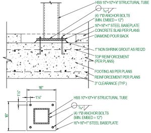
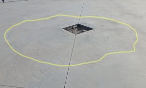
One of the fundamental axioms of concrete is that “concrete cracks.” In conventional (non-post-tensioned) slabs, joints are used to limit the number and width of random cracks that result from normal curing shrinkage of the concrete. However, restraint of the slab from any source can render the joints ineffective and increase cracking potential. Consider the detail provided in the construction drawings for a light-use warehouse (no forklift traffic) slab (Figure 1). The slab-on-ground was detailed such that it was cast directly on top of the interior footing. The slab and footing were constructed as shown in the detail. Unfortunately, a mechanical bond developed between the footing and the slab, thereby restraining the slab. The result was a circular crack in the slab all around the column block out (Figure 2). Similar cracking developed around seven of the eleven column locations. The guidelines of ACI 360R state: “Every effort should be made to avoid connecting the slab to any other element of the structure.” By simply lowering the footing and placing base material between the slab and the footing, or using slip sheets or other methods to prevent the bond between the slab and the footing, the cracking could have been prevented (see ACI 360R Figures 6.2 and 6.3).
Example 2: Boiler-Plate General Notes
The author was recently asked to evaluate a contractor’s decision to place a 35,000-square-foot slab-on-ground in a single day continuous pour operation. A general note in the construction drawings stated:
Large areas of interior slabs on grade shall be placed in strips not to exceed 120 feet in length nor 30 feet in width which are subdivided into roughly squares whose sides shall not exceed 15 feet in either direction.
An opposing party contended that the work was defective because the slab was placed without regard to the pour limits shown. In this case, the contractor used a laser screed, power trowels, and early entry concrete saws to accomplish the slab construction. There is nothing in ACI limiting the size of a concrete pour. ACI 302.1R states, in paragraph 10.1.1.1:
Large block placements are the most efficient way to place concrete in large areas. Laser-guided equipment is most often used for this configuration (Fig. 10.1.1a). Laser screeds provide accurate strike-off between construction joints. Strip placements are an acceptable alternative to block placements if a laser screed is not available or access is inadequate.
The size of a pour is limited only by what the contractor has resources and technology to accomplish. Using modern tools and techniques, contractors can successfully place large areas of concrete. It is not unheard of for contractors to place as much as 75,000 square feet or more of slab in a continuous single-day operation. If the contractor had followed the general note, it would have taken at least ten separate pours to complete the slab. The cost of mobilizing, forming, placing, and post pour cleanup of ten individual pours would have been significantly more. It was not appropriate for the design professional to limit the contractor to methods that did not allow them to use modern equipment to perform efficient construction. In this instance, it was ultimately determined that the contractor’s decision had no detrimental effect on the slab and that there was no justification for the limitations of the general note.
Example 3: Construction Joints
Construction joints are created whenever slabs are constructed in multiple pours rather than one continuous pour. Depending on the nature of the slab, it may be necessary to restrain vertical movement of the slab across the joint. A historical method to create a construction joint with vertical movement restraint was the use of a keyway. The current preferred method is the use of dowels. The keyway construction joint is complex and expensive (Figure 3).
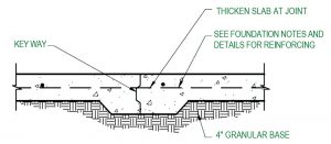
A keyway section must be constructed on-site or pre-purchased, then installed into the formwork. ACI 306R does not recommend keyways in areas of heavy load or wheeled traffic “because the male and female key components lose contact when the joint opens due to drying shrinkage. This can eventually cause a breakdown of the concrete joint edges and failure of the top side portion of the key.” Keyway construction joints are especially problematic at thinner slabs because the slab must be thickened at the joint to provide enough space to construct the keyway. This increases the cost of the excavation, base and subbase preparation, and formwork installation. It also creates horizontal restraint to slab movement that increases the probability of cracking. The “standard detail” was provided in the construction drawings for a 4-inch thick slab-on-ground.
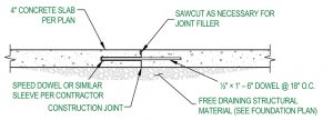
The contractor proposed using smooth dowels, consistent with ACI 360R Figure 6.5 guidelines, as shown in Figure 4. A dispute arose, and the contractor, facing the pressures of keeping the project on schedule, proceeded with slab construction using dowels. Had the design professional been familiar with current preferred construction methods, and updated their standard details accordingly, the dispute could have been avoided. Eventually, this dispute was one factor that led to the issuance of a stop-work order from the owner, culminating in costly litigation.
Example 4: Reinforcing
A common misconception of project owners, some contractors, and the occasional design professional is that the use of reinforcing in a slab-on-ground prevents cracking. Reinforcement does not prevent cracks. Instead, it increases the number of cracks but reduces the crack widths. Options for slab reinforcing to limit crack widths include deformed bar reinforcing, wire mesh reinforcing, and fiber reinforcing. The design professional provided the following specifications for a large, indoor slab-on-ground:
- Interior slabs on grade shall be 4 inches thick
- Reinforce all slabs on grade with #4 bars at 18 inches on-center each way, or with 4×4 W2.9xW2.9 wire mesh.
- Reinforcing steel in concrete shall be securely anchored and tied in place prior to placing concrete and shall be positioned with the following minimum concrete cover:
- Slabs on grade: Center of slab
The contractor proposed using synthetic fiber reinforcing. He was concerned that #4 reinforcing in a 4-inch-thick slab would not provide adequate concrete coverage over the reinforcing. Both ACI 360R and 302.1R discuss the risk of bar shadowing cracking and/or subsidence cracking when cover over reinforcing is not sufficient in concrete slabs. 1½ to 2 inches of cover is generally considered the minimum allowable to reduce the risk of such cracking. The contractor was also opposed to wire mesh reinforcing because he intended to use laser screed equipment to achieve the desired floor flatness and levelness, and supporting wire mesh reinforcing to allow a laser screed to be driven over it is a daunting task. Also, to be effective at limiting crack width, wire mesh reinforcing should be located within the top third of the slab, not in the middle of the slab as specified. The contractor’s proposal was rejected, and ultimately wire mesh reinforcing was installed. The owner was not satisfied with the cracks that developed and commissioned an investigation of the slab, including destructive testing, which revealed that the wire mesh reinforcing varied in its position within the slab, resting against the dirt in some locations and within 1 inch of the surface at other locations.
While the contractor was not relieved of his responsibility to place the wire mesh in the specified location, it is doubtful that the mesh placement at the center of the slab would have achieved results acceptable to the owner. ACI recognizes that both synthetic macro fibers and steel fibers can reduce plastic cracking and drying shrinkage cracking. In addition to reducing visible cracking, steel fibers can increase shear strength, and impact resistance and flexural toughness of concrete slabs. If fiber reinforcing had been permitted, perhaps a slab that satisfied the owner’s expectations would have resulted.
Example 5: Joint Locations and Details
Both ACI 360R and 302.1R state that the design professional should provide the layout of joints and joint details. ACI 360R continues, “When the joint layout and joint details are not provided before project bid, the designer should provide a detailed joint layout along with joint details before the slab pre-construction meeting or commencing construction” (emphasis added). Does this boiler-plate general note adequately provide the layout of joints for a slab?
Control joint spacing rule of thumb is 24x slab thickness
(4” slab = 8’-0” max O.C. each way)
For a residential sidewalk, the note may be enough. For the 40,000-square-foot commercial slab-on-ground with a dog-leg geometry, where the note was the only information provided, a dimensioned control joint plan should have been created.
Design professionals have a direct impact on the outcome of concrete slab-on-ground construction. Whether that impact is positive or negative depends on the designers’ understanding of slab construction and the heed given to provide specifications and details consistent with current technology, techniques, and industry standards. If you have never seen a laser screed in action or never witnessed an early entry saw in use, talk to the contractor on your next project and get out to the site. Hit the books, visit concrete industry websites, and read concrete magazines. Do not leave your next concrete slab-on-ground crying for attention.■