
Part 2
This is the second of two articles discussing high-level design considerations of prestressed concrete girders. Part 1 (STRUCTURE, January 2021) provided an overview of the post-tensioning and pretensioning processes, described the common materials used in constructing prestressed bridge girders and discussed the time-dependent prestress losses inherent in their design. The discussion continues in Part 2 with fundamental design considerations for internal stress distributions within prestressed concrete girders and the methodology for application.
Raised, Draped, and Debonded Strands
When straight strands are bonded for the full length of a prestressed girder, the tensile and compressive stresses near the ends of the girder will likely exceed the allowable service limit state stresses. This occurs because the strand pattern is designed for stresses at or near midspan, where the dead load moment is highest and can best balance the effects of the prestress. Near the ends of the girder, this dead load moment approaches zero and is less able to balance the prestress force. This results in tensile stresses at the top of the girder and compressive stresses at the bottom of the girder.
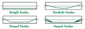
With a raised strand pattern, the center of gravity of the strand pattern is raised slightly and is a constant distance from the bottom of the girder for the girder’s entire length. Other strand configurations are available, as shown in the Figure. Draping some of the strands is another available method to decrease stresses from prestress at the ends of the I-beam, where the stress due to applied loads is at a minimum. Note that all the strands that lie within the “vertical web zone” of the mid-span arrangement are used in the draped group. The designer may also use debonded strands. Partially debonded strands are fabricated by wrapping sleeves around individual strands for a specific length from the ends of the girder, rendering the bond between the strand and the girder concrete ineffective for the wrapped or shielded length. Preference for each of these methods is on a state-by-state basis. For example, Wisconsin’s order of preference for strand placement is straight, draped, and then partially debonded. For the Michigan Department of Transportation (MDOT), debonding is the preferred method of controlling stresses at the end of I-beams, and draped strands should be avoided where possible.
Strand Development, Transfer, Anchorage, and Spacing
Development length is the shortest length of a strand in which the strand stress can increase from zero to the yield strength. If the distance from a point where the strand equals the yield strength to the end of the strand is less than the development length, the strand will pull out of the concrete.
Transfer length represents the first portion of the development length over which the prestressing strand should be bonded so that a stress in the prestressing strand at the nominal strength of the member may develop. A short transfer length increases stresses and the risk of cracking by concrete splitting, bursting, or spalling in the end regions. A long transfer length reduces the available member length to resist bending moment and shear and therefore increases member cost. A pretensioned member’s design strength is taken as the nominal strength multiplied by the strength reduction factors in sections within the transfer length and the development length. If a critical section occurs within these regions, where the strand is not fully developed, failure may occur by bond-slip (Building Code Requirements for Structural Concrete and Commentary, ACI 318-11).
Bond stresses are derived through a combination of adhesion, friction, and mechanical interlocking. It has been widely believed that a wedging effect, unique to pretensioned strands, creates significant bond stresses in the transfer zone. The effective prestressing force is transferred from the pretensioned strand to the concrete. In those same regions, slip occurs between strand and concrete due to the difference in strain condition. Research has indicated that the strand end slip can be used as a quality control measure for the bond of prestressing strands. Furthermore, the relative slip between strand and concrete virtually ensures that adhesion plays little or no role in transferring prestressing forces to concrete.
Historically, the American Association of State Highway Transportation Officials (AASHTO) limited the strand clear spacing to a minimum of three times the strand diameter. In bridge codes before the AASHTO Load and Resistance Factor Design (LRFD) Bridge Design Specifications, this provision was made an explicit part of the design code. This code provision likely mirrored the standard of placing 0.5-inch strands at 2.0-inch, center-to-center (c/c) spacing. If this provision were extended to the larger diameter 0.6-inch strands, then the 0.6-inch strands would have to be placed at 2.4-inch c/c. Nevertheless, using this strand spacing would cancel out the economic value inherent in using a 0.6-inch strand. It would also cancel out the most compelling reasons to use high-strength concrete in pretensioned girder applications. Russell (1994) showed that 0.6-inch strands must be placed at a spacing of about 2.0-inch c/c to enable designs to take advantage of high-strength concrete. Cousins et al. conducted a series of tests in 1993 and concluded that the strand spacing had no effects on the measured transfer and development lengths.
Design Methodology
There are three primary stages to be addressed in prestressed girder design: transfer, service, and ultimate. The California Department of Transportation’s (Caltrans’) 2018 Bridge Design Practice Guide describes them succinctly:
- Transfer refers to the stage at which the tensile force in the strands is transferred to the Precast (PC) girder by cutting or detensioning the strands after a minimum girder concrete strength has been verified. Because the girder is simply supported and only self-weight acts with the prestressing at this stage, the most critical stresses typically occur at the ends of the girder or harping points (also known as drape points). Both tensile and compressive stresses should be checked at these locations against AASHTO LRFD stress limits.
- Service refers to the stage at which the girder and deck self-weight act on the non-composite girder, together with additional dead loads (e.g., barrier and wearing surface) and live loads on the composite section. This stage is checked using the AASHTO LRFD Service I and III load combinations, per Caltrans Amendments, Table 5.9.4.2.2.-1. The girder must also be designed to prevent tension in the precompressed tensile zones (“zero tension”) due to permanent loads.
- Ultimate refers to the Strength Limit State. Flexural and shear strengths are provided to meet all factored load demands, including the Caltrans P-15 design truck (Strength II load combination).
Generally speaking, the mechanics present in prestressed beams are similar to non-prestressed beams. The principles of flexural, shear, and torsional forces must be understood and accounted for in the design. The inclusion of prestressing strands, however, modifies some of these characteristics. The modifications primarily occur in the flexural/moment realm of element design through beam-end reactions and continuity moments. They can also affect the shear resistance of an element due to bursting considerations. A secondary design consideration is the prestressing forces at release, or transfer, which produce temporary tensile stresses at the top of the concrete member and need to be checked to ensure that they do not exceed the concrete’s tensile capacity. Additional longitudinal reinforcement in the bridge deck is generally required near piers to provide adequate moment capacity for negative bending.
The amount of reinforcement is that which is sufficient to resist the total tension force in the concrete based on an uncracked section. For draped designs, the control is at the hold-down point of the girder. At the hold-down point, the initial prestress is acting together with the girder dead load stress. This is where tension due to prestress is still maximum, and compression due to girder dead load decreases. For non-draped designs, the control is at the end of the member where prestress tension exists but where dead load stresses do not occur.
As the bottom fibers of bridge girders encounter prestressing losses (this is where most of the prestressing strands are focused), the girders gradually encounter upward camber and beam-end moments. The beam-end rotations would continue to grow unless restrained. Current design methodology accounts for this phenomenon and restrains the beam-ends by inducing continuity through the spans of a bridge.
Deck-only continuity is when deck joints over the beam-ends are eliminated, and the deck itself acts as a hinge for the composite structure. In this case, the beams are designed as simple spans, and the reinforcing steel within the deck must be designed for compatibility with the girder rotations.
Full-section continuity is similar to deck-only continuity, except that the girders’ bottom flanges are tied together, and the space between the composite section of the deck and girders is sealed with a concrete closure pour. Full-section continuity allows a series of girders to act as a single girder placed continuously over a bearing.
AASHTO LRFD Article 5.14.1.4.5 defines two joint types: a fully effective joint, which treats the structure as continuous for all limit states, and a partially effective joint, which treats the structure as continuous for the strength limit state only.
Effects on Design for Flexure
Positive moment requires prestressing force below the section centroid; negative moment requires it above the centroid. The required eccentricity of prestressing tendons with the section’s centroid increases with increased applied bending moment. Curved tendon profiles that approximately follow the shape of the appropriate bending moment diagram are not easily feasible in pretensioned members, so general tendon profiles have been established for design purposes.
Effects on Design for Shear and Torsion
Orangun et al. (1977) indicated that transverse reinforcement confines the concrete around anchored bars and limits the progression of splitting cracks.
Edge girders encounter torsion due to the eccentricity of their loading of the main deck slab, barrier and parapet walls, and/or cantilevered components. In some cases, edge girders are loaded in torsion by (floor) beams framing into them from the sides between the ends of the girder. The beam’s free-end rotation is retrained by the girder’s torsional stiffness and is, therefore, a design consideration.
Trends of Prestressed Girders
The AASHTO LRFD Bridge Design Specifications contains restrictions on the use of high-strength concrete due to the lack of previous performance history and empirical data available. These restrictions limit the application of existing and new technology to bridges. Concretes with design compressive strengths above 10 ksi shall be used only when allowed by specific articles of the specifications or when physical tests are made to establish the relationship between the concrete strength and other properties. Revisions in design guidance will continue as data becomes increasingly available, leading to a broader array of high-strength concrete applications.
The lessons learned and knowledge base of prestressed concrete girders are being leveraged into other structural design aspects. Practitioners worldwide are beginning to realize the stakeholder benefits and time-saving possibilities of employing the principles of prestressed concrete in other, more irregular shapes. For example, Accelerated Bridge Construction (ABC) is predicated on the idea of designing elements to be constructed off-site using prestressed technologies and rapidly deploying them on site.
Conclusion
Prestressing losses are characteristic of composite members once they are cast and affect the ultimate utility of the design. Elastic shortening, shrinkage, and creep all affect the design life and efficacy of prestressed concrete beams. The current methodology tries to consider and account for the interaction of these phenomena to develop an effective design. This highly complex process is the result of the bridge designer’s iterations over many years.■
References
American Concrete Institute (ACI). Building Code Requirements for Structural Concrete and Commentary, ACI 318-11, Detroit, 2011.
Beal, D. NCHRP Report 603: Transfer, Development, and Splice Length for Strand/Reinforcement in High-Strength Concrete, Foreword, Transportation Research Board, Washington D.C., 2008.
Caltrans Bridge Design Practice Guide Chapter 8: Precast Pretensioned Concrete Girders, California Department of Transportation, Sacramento, CA, 2015.
Cousins, T.E., Stallings, J.M., and Simmons, M.B. Effect of Strand Spacing on Development of Prestressing Strands, Alaska Department of Transportation and Public Facilities, Juneau, AK, 1993.
Marti-Vargas, J. and Hale, W.M. Predicting Strand Transfer Length in Pretensioned Concrete: Eurocode versus North American Practice, American Society of Civil Engineers, 2013.
MDOT. Bridge Design Manual Chapter 7: LRFD, Vol. 5, Michigan Department of Transportation, Lansing, MI, 2019.
Orangun, C.O., Jirso, J.O., and Breen, J.E. “A Reevaluation of Test Data on Development Length and Splices.” ACI Journal of Proceedings, 74(3), 114-122, 1977.
Parsons Brickerhoff. Example No. 1: Prestressed Concrete Girder Bridge Design, New Mexico Department of Transportation, Sante Fe, NM, 2011.
Raja, N. Thesis: Design of Prestressed Concrete Girder Bridge, Edith Cowan University, Perth, Western Australia, 2012.
Ramirez, J. and Russell, B. NCHRP Report 603: Transfer, Development, and Splice Length for Strand/Reinforcement in High-Strength Concrete, Transportation Research Board, Washington D.C., 2008.
Rose, D.R., and Russell, B. “Investigation of Standardized Tests to Measure the Bond Performance of Prestressing Strand.” PCI Journal, 42(4), 56-80, 1997.
Russell, B.W. “Impact of High Strength Concrete on the Design and Construction of Pretensioned Girder Bridges.” PCI Journal, 39(4), 76-89, 1994.
Russel, B.W., and Burns, N.H. “Measured Transfer Lengths of 0.5 in. and 0.6 in. Strands in Pretensioned Concrete.” PCI Journal, 41(5), 44-63, 1996.
Wight, J. Reinforced Concrete Mechanics and Design, 7th Ed., Pearson, Hoboken, NJ, 2016.
WisDOT. WisDOT Bridge Manual Chapter 19 – Prestressed Concrete, Wisconsin Department of Transportation, Madison, WI, 2019.