
Due to damage or deterioration, structures, infrastructures, and even vehicles may require in-situ repairs and modifications. This is true for structures that are on land but also for those underwater. Piers in ports deteriorate or get damaged by impact or operations over time, and ships and vessels require maintenance and repairs below the waterline.
Topside (on land) welding codes like the American Welding Society’s AWS D1.1, Structural Welding Code, strictly prohibits welding and thermal cutting on wet surfaces or in the rain. Accelerated cooling rates could result in faulty welds with discontinuities in the weld that could lead to the failure of the structure.
This article introduces the basics of underwater wet welding, including two case studies for underwater repair – a pier in the port of Kiel in Germany and the underwater repair of two rudders on a cruise ship in various ports in the Caribbean.
Underwater Wet Welding
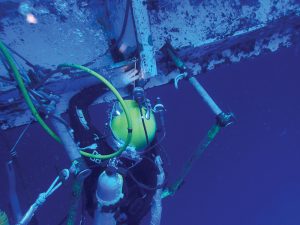
Per AWS D3.6, Underwater Welding Code, underwater wet welding is performed at ambient pressure with the welder diver in the water without any physical barrier between the water and the welding arc (Figure 1).
Konstantin Konstantinovich Khrenov, an engineer from the Soviet Union, is credited with the first underwater wet weld performed in 1932. During WWII, underwater wet welding gained acceptance by the U.S. NAVY as an emergency repair method and for salvage operations. In the late 1960s and early 1970s, underwater wet welding gained new momentum with the emergence of the offshore oil and gas industry.
Quality of Underwater Wet Welding
Five major factors influence the quality of underwater wet welds. With the introduction of the following key factors, underwater wet welding can be consistently performed for permanent repairs on all types of underwater structures.
Wet Weldability of Materials
Wet welding is completed in an environment that is hostile to both the weld and the welding process. Welding in a wet environment results in greater cooling rates and produces significant amounts of martensite (a very hard and brittle form of a steel crystalline structure) in the heat-affected zone (HAZ) for nearly all low-carbon steels. Materials with a higher carbon equivalent (CE) may exhibit a high martensitic microstructure and become increasingly crack susceptible.
The International Institute of Welding (IIW) formula is used to calculate the CE to determine the wet weldability of the base metal.
The generally accepted CE upper limit for wet welding using ferritic electrodes is 0.4%. The ideal materials for wet welding exhibit a CE ≤ 0.38 percent with a carbon content C ≤ 0.16 percent.
The Shielded Metal Arc Welding (SMAW) process using a coated electrode (Process 111 in ISO 4063) is the most common welding process used in underwater wet welding.
Environment
The welding process and/or the quality of the weld being produced can be severely affected by environmental issues. Poor underwater visibility can affect the welder diver’s ability to see the arc and to inspect the resultant weld. Swells, waves, water currents, or vessel movements can have a detrimental effect on the welder diver’s ability to remain stable. Contaminated water may require special diving suits, which may restrict the movement of the welder diver. Contamination of the water or materials may affect the weld properties. Depth of water has a direct effect on weld quality, in particular porosity and ductility.
Personnel
Welder divers should be experienced commercial divers holding an applicable national or international commercial diving qualification and be suitably trained, competent, and experienced in wet welding. Historically, it was assumed that qualified and experienced topside welders could easily apply their skills underwater without the need for further training. In practice, individuals can rarely adapt without additional training. It is well noted that most experienced top site welders find it difficult to break habits that work fine on the surface but are difficult, if not impossible, to apply underwater.
Wet Welding Electrodes
Welding electrodes are comprised of a filler (core) wire, which has a flux covering extruded along its length, except for approximately 1 inch left bare to allow contact in the electrode holder. The filler wire is of high quality but lean in terms of alloying elements. The flux coating is a mixture of compounds and elements that contain all the alloying elements that change the ‘as welded’ weld metal to give the weld metal the desired properties. The flux coating also provides slag and gas formers, de-oxidizers, chemical cleaners, and other additions as applicable to the type of electrode.
Wet welding electrodes are manufactured in the same way as conventional surface welding electrodes. However, they include a waterproofing or additional protective coating. Historically, wet welding was completed using surface welding electrodes either covered in insulation tape or dipped in wax, lacquer, or paint. While some of them produced reasonable looking welds, their mechanical properties and user-friendliness were comparatively poor. Weld quality has significantly improved with the development of new purpose-built welding electrodes.
Equipment
Finally, the equipment used in underwater wet welding can have an impact on the quality of the final product. There are basic wet welding equipment requirements that should be met to comply with safety regulations and welding procedure requirements.
Underwater Welding Codes
The worldwide established underwater welding code for hyperbaric dry and wet welding is AWS D3.6M, which specifies three weld classes (A, B, and O), encompassing a range of quality and properties. Class A welds are intended to be suitable for applications and design stresses comparable to conventional surface welded counterparts. In contrast, Class B welds are intended for less critical applications where lower ductility, moderate porosity, and other limited discontinuities can be tolerated. Class O underwater welds must meet requirements of another designated code/standard, as well as additional requirements specified in AWS D3.6, to cope with the underwater welding environment.
Following are two case studies: one describes the underwater wet weld repairs of erosion/cavitation damage of the side rudders of a cruise ship performed during regular port stops. The second case study introduces the renovation of a sheet pile pier at a ferry terminal using complex underwater wet welding techniques.
Cruise Ship Repair
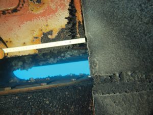
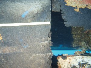
An in-water survey, performed by divers on the underwater part of a 317-yard-long and 125,323-gross-tonnage cruise ship revealed heavy cavitation and erosion damage caused by galvanic corrosion on the inboard and outboard side of the port and the starboard rudder. The port side rudder revealed a total section loss in some areas of the rudder plating, which caused the rudder to flood with seawater (Figures 2 and 3).
After the damage was observed, a repair plan was developed that would keep the vessel out of dry dock and not interfere with the itinerary of the vessel. The divers would sail with the vessel and perform the work during regularly scheduled port stops.
Repair Plan
The first step was to determine the extent of the damage via an inspection dive. Material certificates for the steel used on the rudders were not available. Since a chemical composition is required to determine the wet weldability of the material, steel samples were retrieved from the rudder during the inspection dive. The results of the analysis were within the limits of wet weldability. A repair plan was developed to clean and restore the deteriorated areas to the original plate thickness. Some of the rudder plating in specific locations could be cropped. The leading edge of the rudder with total section loss was repaired with a doubler plate that matched the curvature of the leading edge.
Welding
All welding was performed underwater employing underwater wet welding techniques following the submitted and approved repair procedure and with the class approved Procedure Qualification Records (PQR) and Welding Procedure Specifications (WPS).
Underwater welding was performed employing the wet SMAW with Hydroweld FS underwater wet welding electrodes.
The finished welds met the requirements of Class A underwater welds per ANSI/AWS D3.6M:2010. The mechanical properties of Class A welds per AWS D3.6 are comparable to topside welded connections.
Completion
A total of approximately 4,500 underwater wet welding electrodes were used to restore the cavitated/eroded sections of the rudders. In some locations, the original plate thickness of 19⁄16 inches was deteriorated to 5⁄16 inches. It took the dive teams six attendances, each lasting 2 weeks, to repair the damages. Diving was performed during scheduled port stops without interrupting the itinerary of the vessel.
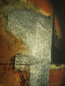
Figure 4 shows the completed build-up welds in a particular area on the port side rudder.
Pier Renovation in Kiel, Germany
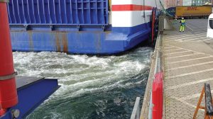
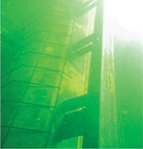
The sheet pile wall of the Stena Line pier was found to be heavily corroded over a length of approximately 1,000 feet. Typically, corrosion damage on sheet pile piers is contained within the splash or tidal zones, 3 feet above and 5 feet below the waterline. However, this sheet pile wall was different and exhibited corrosion holes with total section loss into the mudline, to a depth of approximately 36 feet. One of the reasons for the unusual corrosion pattern was due to the daily arrival and departure of the largest Stena Line ferries. The propellers on the three bow and two stern thrusters of these vessels stir up the water, bringing oxygen to the bottom and causing heavy corrosion to the sheet pile wall (Figure 5).
Repair Plan
Two different solutions were discussed for the repair of the pier. The first discussion was a completely new construction of the entire pier over a length of approximately 1,000 feet, which required the pier to be closed during construction. All daily handling activities, including trucks, trailers with containers, as well as cars and passenger traffic, would have to be diverted to another pier, an almost impossible task in the relatively small port of Kiel.
The second option considered the renovation of the sheet pile wall during day-to-day operations by divers, mostly during night shifts. This solution was chosen since it did not affect the operation of the pier.
The most significant advantage of the renovation compared to a new build was reduced cost, despite relatively expensive labor costs resulting from diving activities performed primarily during night hours. Additionally, the operation of the ferries was not affected.
The approach for the repair of the pier was planned and executed as follows:
- Installation of prefabricated reinforced steel forms that wrapped around the existing sheet pile wall,
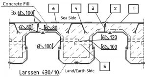
- Installation of support brackets (Item 5 in Figure 6) inside the sheet pile fields between the upstream and downstream wall,
- Installation of structural T-profiles (Item 2 in Figure 6) welded with shear tabs to the seaside face of the existing sheet pile wall, and
- Installation of sealing plates (Item 1 in Figure 6).
The Repair
To gain access to the bottom of the sheet pile wall, approximately 3,200 cubic feet of mud, silt, and scrap had to be removed and relocated by divers, with the help of pumps, from the base of the sheet pile wall.
The next step was the cleaning of the existing sheet pile wall. Approximately 32,000 square feet of the existing sheet pile wall had to be cleaned from marine growth, loose rust, and other foreign material by divers with a pressure washer at an operation pressure of 4.650 ksi.
A total of 20 U.S. tons of reinforcing steel, including 660 pieces of prefabricated reinforced steel forms that wrapped around the existing sheet pile wall, were installed and followed the contour of the existing sheet pile wall, held in position with welded shear tabs.
Structural U 140 channels (5.5 x 2.5 x ¼ inches) were used to fabricate the braces to be installed between the upstream and downstream walls of the existing sheet pile wall. A total of 890 braces (5 U.S. tons) were installed at different elevations.
39 U.S. tons of structural profiles T 120 (Item 2 in Figure 6), each approximately 25 feet in length, were welded onto the seaside face of each sheet pile field to guide and secure the seal plates into position. The T 120 structural profiles were welded with shear tabs 6 x 3 x ½ inches to the seaside face of the existing sheet pile wall (4,611 pieces) (Figure 7).
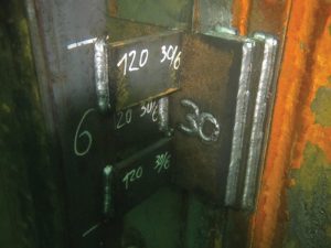
Adjustment tabs were used to fine-tune and to align the T 120 structural profiles and to support the sealing plates (Figure 8).
567 pieces of sealing plates (Item 1 in Figure 6) fabricated from ½-inch-thick higher tensile steel S355 were installed. The sealing plates were installed from the bottom to top elevation in between the T 120 structural profiles. They were secured in position with stitch welds between the plates and the T 120 on the sides, and with weld tabs on the top and bottom. Three seal plates were used to achieve the required height. The height of the plates varied between 94.5 inches and 102.4 inches.
A total of 1,850 feet of linear welds were produced by underwater wet welding techniques to connect all structural components. All structural welds were executed as multiple layer fillet welds by welder divers certified to EN ISO 15618-1.
The approximately 1,850 cubic yards of C35/45 underwater concrete was poured in three separate lifts using the tremie method. After each pour, the concrete was allowed to cure completely. Prior to the next pour, the laitance layer on top of the concrete was removed with a high-pressure cleaner.
Summary
Today, the introduction of steels with chemistries more favorable to underwater wet welding (C ≤ 0.16 percent and C.E. ≤ 0.38 percent), welding electrodes developed explicitly for underwater wet welding applications, managed training programs, and improved welding techniques have greatly improved options for underwater welding. Underwater wet welds in groove and fillet welds can achieve comparable mechanical properties and nondestructive evaluation (NDE) results as their top site welded counterparts.
The two case studies show that complex underwater projects can be completed meeting top site engineering requirements without building expansive habitats, which would allow the work to be performed under dry conditions.■
References
American Welding Society (AWS), D3.6M:2017 Underwater Welding Code, 6th Edition, AWS D3 Committee on Marine Welding, Miami Florida
Pett, Michael, Practical Guide to Underwater Wet Welding, Hydroweld, www.hydroweld.com