
Which End to Stress First?
In post-tensioned floors, tendons are stressed after cast concrete gains adequate strength. The stressing operation is monitored to ensure that tendons receive their design-intended force.
Three questions on tendon stressing are often raised among post-tensioning crews. These are:
- What is the right sequence of tendon stressing when the structure has multiple tendons with different arrangements, such as common two-way slab systems.?
- When long tendons are marked for stressing at both ends, which end should be stressed first and what is the right order for correct elongation measurement?
- How are the stressing records reconciled when the elongation measurements are outside the target limits?
This article covers the first two questions. A follow-up article will address the third.
Stressing Sequence
When there is more than one tendon or one tendon group in the construction, one question is – which tendon group to stress first?
The following text is from the General Notes of a typical construction document for post-tensioned floors.
The general tendon stressing sequence for one-way systems shall be as follows:
First: uniformly distributed tendons;
Second: beam tendons;
Third: girder tendons.
The General tendon stressing sequence for two-way systems shall be as follows:
First: uniformly distributed tendons;
Second: banded tendons.
Continuous tendons in multi-span beams (girders) shall be stressed before any non-continuous tendons.
To fully appreciate the significance of the above instructions and their applicability, two considerations are important.
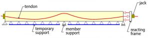
First, in standard construction, the entire floor is resting on forms at the time of stressing. Post-tensioning results in bending stresses in the slab or beam only if the uplift from the post-tensioning tendons is greater than the self-weight of the member being stressed. Bending stresses result from a change in the curvature of the member. If the member being stressed remains in contact with its support, its curvature does not change – hence no bending stresses (Figure 1).
Second, in standard building construction, post-tensioning for slabs or beams is typically selected to provide uplift between 60% to 80% of the member self-weight, or, in the case of beams, the self-weight of the beam and the reaction from members that shed load on the beam. Again, if, at stressing, the post-tensioning is not large enough to lift the members that load the beams, the distribution of load among the members’ envisaged in-service conditions does not occur.
The following illustrates that, for common conditions, standard design parameters do not favor a specific stressing sequence.
Beam and One-Way Slab Construction
Figure 2 shows a post-tensioned beam and one-way slab construction. The slab and beam tendons are each profiled to counteract their respective self-weights.
Apart from its own weight, the beam carries the reaction from the slab it supports. The question on stressing sequence reduces to the following: Does stressing of the slab before or after beam stressing impact the beam’s performance either during the construction or when in service?
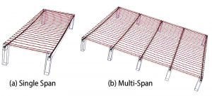
For the single-span slab shown in Figure 2a, the slab reaction on the beam does not depend on whether or not the slab is stressed and how much of the slab weight is balanced by post-tensioning. The slab reactions, as shown in Figure 3, remain unchanged. The load on the beam is independent of the state of stressing in the slab. For this reason, it is immaterial whether the beam or the slab is stressed first. Likewise, the stressing of the beam does not impact the response of the slab. The sequence of stressing can be based on the expediency of construction. The other consideration is that the beams are rarely designed to provide uplift beyond their own weight and the reaction of the slabs they support. The beam is not likely to lift off its support when stressed first.
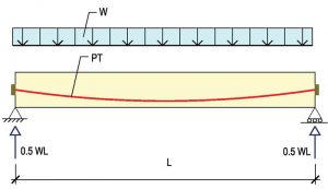
Figure 2b shows a multi-span member, such as slabs over parallel beams. In this case, the slab reactions on the beam depend on whether the slab tendons are stressed or not – tendon stressing changes each of the reactions from gravity by the hyperstatic forces from prestressing. The question is whether the change in the slab reaction on the beam arising from slab stressing is large enough to impact the beams’ response.
Referring to Figure 2b, where the slab spans over several beams, the load on the beams will be different depending on whether the slab is stressed. In this case, in principle, the sequence of stressing matters. But, since the hyperstatic reactions from prestressing are generally much smaller than the reactions from self-weight, the sequence of stressing is not viewed as consequential. Again, the question is addressed since, at stressing, the slab and beam are both supported.
In summary, for either single or multi-span beam and slab construction, the sequence of stressing may be based on the convenience of construction. Each member may be stressed in full before moving to the next.
Two-Way Slab Construction
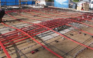
There are several options in the tendon layout of two-way slabs. Figure 4 is a partial view of a two-way slab illustrating the typical banded-distributed layout of tendons.
Two questions arise in connection with the sequence of stressing: first, whether the sequence of stressing will result in local over-stress at construction. Second, whether the sequence will change the resulting load-carrying characteristic of the floor system when in service.
In practically all constructions, the post-tensioning is fine-tuned to balance a fraction of the member’s self-weight, typically 50% to 80% – not more than the member’s total weight at stressing. Hence, the slab will not lift off the form support. Extreme fiber bending stresses will form only if stressing results in a change in slab curvature.
The common practice is that distributed tendons are stressed first. As an example, for the condition shown in Figure 4 with interior spans at 29 feet and slab depth at 7.5 inches, the uplift from the post-tensioning of banded tendons must exceed 80% of the slab’s self-weight before the slab partially lifts off the form. The sequence of stressing is not critical to the stress condition of the slab either at stressing or when in service. The convenience of construction favors stressing sequence.
Stressing Sequence
When a long tendon is marked to be stressed at both ends, the following questions arise.
(i) Which end should be stressed first?
(ii) Should one end be stressed to full value and seated before stressing the other end? Or, should one end be partially stressed, be seated, and the second end stressed to completion?
(iii) Should both ends be stressed simultaneously?
Briefly, at stressing, the jack pulls the prestressing strand out of the anchor piece. Once the jacking force reaches the design value, the strand is anchored at the face of the member. The common anchoring mechanism is by way of wedges that grip the strand. The retraction of the wedges into the conical cavity of the anchorage grips to lock the pulled strand into position.
In Post-Tensioned Buildings: Design and Construction (2014), the author provides the details of the stress loss in the tendon and other considerations that govern the force in the tendon at stressing and long-term effects. The focus of the following is a sequence of stressing and measurement of tendon elongation.
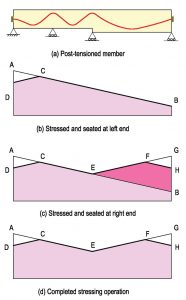
Figure 5a shows a post-tensioned member to be stressed at both ends. The common practice is to stress one end to its design force, seat it, stress the second end to its design force, and seat the second end. Tendons are simultaneously stressed at both ends only in special circumstances. The common practice is to stress the tendon ends to full force, one end after the other.
Under full force at the left end, the distribution of force in the tendon is shown by line AB (Figure 5b). The distribution is shown by a straight line to explain the concept. The force drop along the tendon length is governed by the tendon’s geometry and the tendon’s other properties. It is close to a straight line.
Point A marks the tendon force at maximum jacking pressure. Once seated, the retraction of the wedges into the anchor cavity results in some stress loss. Once fully seated, the tendon force diagram is shown by line DCB. ACD is the stress loss from the retraction of the wedges.
The extension length of the strand after it is seated is proportional to the area below the curve DCB. The larger the area, the longer is the extended length of strand protruding out of the anchor block. The extended length beyond the anchor block is referred to as tendon “elongation.”
The direct correlation between the force in the tendon, given by the area below the force diagram, and the elongation of the strand, evidenced by its extended length out of the member, is used to verify the successful jacking operation. For successful stressing, the tendon elongation is matched against the area below the stressing curve (Figure 5b).
Figure 5c shows the force diagram after stressing and seating of the second end. BEFH marks the change in the tendon’s force diagram resulting from stressing and seating of the second end.
The extension length of the strand after stressing of the second end is proportional to the area BEFH. Comparing the area below the force diagram associated with the stressing of the first end and that of the second end, it is evident that the elongation of the tendon at the second end is less than that of the first end.
The final force diagram of the tendon, when stressed in full and seated, is shown in Figure 5d. Irrespective of the stressing sequence, if during the stressing operation, at some point and each end, the tendon is pulled to the design force (points A and G), the final force diagram will be DCEFH. And the sum of the elongations of the two ends will be proportional to the area below DCEFH.
From the preceding, the successful stressing operation of the tendon is measured by matching the sum of the elongations at the two ends against the calculated value based on the area below the diagram DCEFH.
In summary, the sequence of stressing a tendon (or whether the stress at one end is applied partially and followed by stress at the other end before completing the stress at the first end) does not impact the total elongation and the force distribution in the tendon. This is on the premise that the stressing operation is concluded when each end, at some point, has been stressed to the full value.■
Reference
Aalami, B. O. (2014). Post-Tensioned Buildings; Design and Construction, Book; www.PT-Structures.com; pp. 450.