
This article is a compilation of questions that have been asked of the NCSEA Wind Engineering Committee. The referenced code is the American Society of Civil Engineers’ ASCE 7, Minimum Design Loads for Buildings and Other Structures. The Figures noted here are found in ASCE 7-16.
What wind load should I use on a handrail of a balcony? As with all things related to wind loads on buildings, it is important to envision airflow around the element. For a balcony, there are two important considerations when determining wind load on the railing.
The first consideration is the geometry on the leeward side of the balcony rail. When air flows up and over the railing, a shallow balcony does not have enough depth to develop negative pressure on the backside of the railing. Thus, for a balcony with a depth of 6 feet or less, the wind load on the railing is similar to the load on the building windward wall (Cp = 0.8, per Figure 27.3-1 in ASCE 7-16). There is no need to consider a simultaneous leeward or suction pressure on a railing of a shallow balcony. However, suppose the balcony is deeper than 6 feet. In that case, it is important to consider the effect of negative pressure building up on the backside of the railing in addition to the positive pressure on the front face. As the balcony gets deeper, this combined pressure begins to approach a parapet pressure.
The second consideration that affects wind load on a railing is the material of the railing. A solid glass railing has the capacity to develop negative pressures. A perforated or open railing cannot develop significant negative pressures. A solid surface is required to prevent wind from flowing through the railing and force the flow to go up and over the railing in order to develop negative pressures.
Why did ASCE 7 decide to go from allowable to ultimate wind speeds? Why do we have multiple maps instead of a single map modified by an importance factor?
Prior to ASCE 7-10, the Standard utilized a single map and adjusted the wind speed using a wind importance factor (Iw = 0.77, 0.87, 1.0, 1.15) and a wind-load factor (1.6 for strength design). Beginning with ASCE 7-10, the Standard leverages three (four in ASCE 7-16) maps presented at a strength level (1.0 wind-load factor for strength design) and eliminates the wind importance factor, Iw.
There are several reasons for these changes. First, multiple maps remove the inconsistencies inherent to the importance-factor approach. Importance factors must vary between hurricane and non-hurricane zones, and even across the hurricane coastline, to provide equal risk. With multiple maps, a distinction may be made based on location. The strength level maps establish a more uniform return period for the design-basis winds. Also, strength design wind speed maps bring the design approach used for wind in line with that used for seismic loads. Lastly, the maps more clearly inform owners and engineers about the storm intensities for which designs are performed.
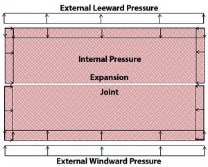
ASCE 7 says I cannot consider shielding. Do I have to design each portion of a building with expansion joints as an independent structure that receives both windward and leeward pressures?
When considering a building with an expansion joint, it is important to recognize that internal pressures do not cancel for the structure on each side of the joint in the direction perpendicular to the joint. In addition, when applying the required wind load distribution on the building, the resistance is not transferred across the expansion joint. As a result of the unique geometry of an expansion joint building, it is important to consider future conditions for the building.
A large warehouse is a typical building for which an expansion joint is added to relieve stresses due to thermal expansion or contraction. For structures with an internal expansion joint, where the building must exist on both sides of the joint for the building to remain operational, it is reasonable to consider only the windward loads on the windward wall and leeward loads on the leeward wall and ignore any external pressures at the expansion joint. If something happened to cause the structure on one side of the building to be damaged or removed, the structure on the adjacent side of the expansion joint would also be demolished or reinforced to act as a standalone structure.
However, if a structure is being built adjacent to an existing structure, it should be designed for the full wind loads assuming the adjacent structure is not there. For example, a parking deck entirely surrounded by residential units should be designed considering a future state for which the adjacent buildings are not present.
What is the difference between wind maps in the ASCE 7 Commentary to Appendix C and the IBC 0.42*W provision?
Unlike seismic drift, which is determined at the strength load level, wind drift is a serviceability concern and should be calculated at the allowable load level. The ASCE 7 Appendix C Commentary presents maps for return periods of 10, 25, 50, and 100 years (Figures CC.2-1 through CC.2-4). These maps adjust the Chapter 26 wind speeds in two ways: 1) They reduce the wind loads from strength to allowable level, and 2) They reduce the Mean Recurrence Interval (MRI 300, 700, 1700, and 3000 in Chapter 26) to 10, 25, 50, or 100 years.
However, the decision of which map to use is not explicitly stated and is left to the engineer’s discretion. The building’s intended usage, the type of cladding materials, and the detailing of the finishes are important considerations when determining the appropriate return period to use for drift calculations.
The International Building Code’s (IBC) Table 1604.3, footnote f, permits the wind load to be taken at 0.42 times the “component and cladding loads for the purpose of determining the deflection limits.” For a Risk Category II Structure, the IBC 0.42 reduction is the equivalent of using the maps in ASCE 7 Commentary for a 10-year return period at a service level wind load.
What is the allowable drift for my Main Wind Force Resisting System (MWFRS) under wind loads?
ASCE 7 does not suggest an allowable drift limit for wind design as it does with a seismic design. However, ASCE 7-16 Appendix CC (Serviceability Considerations) notes that drift limits in common usage buildings should be on the order of 1/600 to 1/400 of the building or story height.
Designers often impose an absolute limit on the interstory drift in light of evidence that damage to nonstructural partitions, cladding, and glazing may occur if the interstory drift exceeds about 0.4 inches. This absolute limit on story drift is often taken as ⅜ inches. Thus, for a building with a floor-to-floor height greater than 12.5 feet, the absolute limit of ⅜ inch would control.
Lastly, the ASCE/SEI Prestandard on Performance-Based Wind Design provides additional examples of drift limits for wind.
What is the difference between a parapet and a screen wall on a roof? How close does a screen wall need to be to the edge of the roof to be considered a parapet?
Mechanical equipment screens commonly are used to conceal plumbing, electrical, or mechanical equipment from view. Historically, ASCE 7 has not provided guidance on what wind pressure to apply to these rooftop screens. Several approaches have been used within the industry, including applying parapet pressures, using the solid-freestanding wall provisions, and applying the rooftop structures and equipment provisions (discussed above). Little research is currently available to provide guidance for determining wind loads on screen walls and equipment behind screens.
The ASCE 7-16 commentary to Section 29.5.1 suggests that the provisions for rooftop structures and equipment be used to generate wind forces on screen walls located away from the edge of a building.
Fh = qh(GCr)Af (ASCE 7-16 Equation 29.4-2)
The commentary also alludes to the fact that screen walls located close to a building edge should be designed for parapet pressures. To quantify the appropriate distance from a building edge to differentiate between “parapet” and “rooftop structures and equipment” pressures, the boundary between corner and edge wind Zones (Zones 2 and 3) versus typical roof Zones (Zone 1) provides a reasonable delineation. Therefore, a suggested practice would be that screen walls located in Zones 2 and 3 should be designed for parapet pressures, while screen walls located in Zone 1 can be engineered for a “rooftop structures and equipment” pressure.
My Architect asked me to review a product that is rated for (XX psf or XX mph). How do I figure out if that is allowable or ultimate, or if the mph is ok for this project since it does not account for exposure or building height?
Most product ratings, including glazing, doors, and siding, are rated by the manufacturer using allowable wind pressures. By providing pressures, rather than miles-per-hour, the rating considers the building’s exposure, height, adjacent topography, elevation, and importance. While most products still provide their ratings at an allowable level, the expectation is that they will adjust to ultimate pressures over time. A conversion of allowable to ultimate wind speeds is provided in Commentary Table C26.5-7.
Shingle ratings are a known exception to product data provided based on pressures. Due to the way roof shingles were originally tested and rated, typical product data for shingles is provided in miles-per-hour only. Thus, it is acceptable to approve shingles without consideration for the factors used to convert from miles-per-hour to pressure.
What is the difference between a 3-second gust and fastest-mile wind speed? How are they related?
For years, engineers used the fastest-mile wind speed in ASCE 7, the average speed at which an imaginary airborne particle would travel when moving a mile downstream. Starting with ASCE 7-95, the Standard uses a peak three-second gust wind speed to define wind loads. Three-second gust is the highest average speed measured over a three-second duration. The transition from fastest-mile to 3-second gust reflects the desire to report an engineering wind speed that more closely reflects the values quoted by a weather reporter, who tends to report the highest wind speed measurable.
ASCE 7 Commentary’s Table C26.5-7 provides a comparison of the strength design-based wind speeds used in the ASCE 7-10 and 7-16 basic wind speed (3-second gust) maps and the ASCE 7-05 basic wind speed (3-second gust), in addition to a comparison with ASCE 7-93 basic wind speeds (fastest mile).
What is the relation between hurricane wind speed and building design wind speed? Is my building designed for hurricane category 3, 4, or 5?
ASCE 7 Commentary Table C26.5-2 provides an approximate relationship between wind speeds in ASCE 7 and Hurricane Categories 1-5.
What wind load should I use on a temporary structure? Many engineers attempt to reduce the wind loads applied to temporary structures due to their relatively short design life compared to regular structures. Common temporary structures include concert stages, tents, public art projects, shade structures, and bleachers. There currently is no nationally recognized Standard that specifies design wind loads for temporary structures.
The IBC addresses temporary structures in Section 3103. This section applies to structures erected for a period of fewer than 180 days, but it does not specify how to determine the design loads except to state that “temporary structures and uses shall conform to the structural strength, fire safety, means of egress, accessibility, light, ventilation and sanitary requirements of this code as necessary to ensure public health, safety, and general welfare.”
Some engineers attempt to use the maps for Serviceability in the Commentary to Appendix C to reduce the wind loads on temporary structures. While these maps do adjust for the return period, they specifically state that “the maps included in this appendix are appropriate for use with serviceability limit states and should not be used for strength limit states.”
Other engineers look to ASCE 37, Design Loads on Structures during Construction. ASCE 37 incorporates provisions for adjusting wind loads to reduce them for short-term exposure during construction for up to five years. This Standard provides reduction factors for the design wind speeds in ASCE 7 as a function of construction duration. However, this Standard is intended for buildings under construction, not a temporary structure. It is important to recognize that many of the temporary structures noted above (concert stages, tents, public art projects, shade structures, bleachers) create areas intended for public assembly. The fact that these structures represent a significant risk to human life in the event of a failure is notably different from the expected usage of ASCE 37, which is intended for a construction site.
In light of the lack of specific direction, there is an intent to include guidance on loads on temporary structures for all hazards, including wind loads, in an Appendix in a future ASCE 7 Standard.■