
Part 4: Demolition Special Inspection and Post Demolition Assessment
This four-part series (Part 1, STRUCTURE, November 2019, Part 2, January 2020, Part 3, April 2020) discusses how the collapse of a building during a demolition operation in Philadelphia in 2013, which resulted in several fatalities, led to the enactment of a City Ordinance to prevent similar future calamities. As a result of the Ordinance, the author became involved with the structural investigation, review of the Site Safety Demolition Plan, and Demolition Special Inspections associated with the adaptive reuse of the Apex Hosiery Company Building located in Philadelphia.
Demolition Special Inspection
The Special Inspector maintained a full-time presence on-site during the demolition operation and submitted the documentation of observations required by the Special Inspection clause of the City Demolition Ordinance. The demolition operations generally proceeded as anticipated; however, during the demolition, two incidents occurred that required special attention.
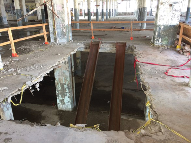
Figure 18. Vehicle access opening cut in the slab during demolition required the installation of shoring posts in the surrounding compromised bays.
The first incident involved the demolition contractor cutting a large, unapproved opening in the SMI slab, as shown in Figure 18, to enable equipment to be driven between the floor levels scheduled for demolition. Subsequent assessment and engineering evaluation indicated that the opening had compromised the structural integrity of several top and bottom reinforcing hoops within the bay containing the opening. As a result, the load-carrying capacity of the immediately adjacent surrounding bays was reduced. The solution submitted by Pennoni to correct the temporary structural deficiency involved the installation of shoring posts in the surrounding compromised bays.
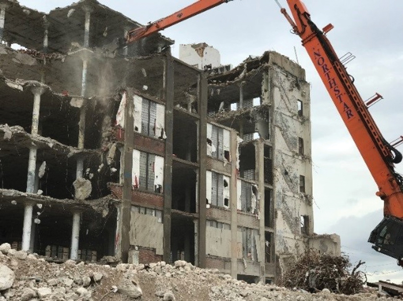
Figure 19. A progressive collapse to the ground floor began on the 4th floor as a result of overloading the floor framing with an excessively large debris pile.
The second incident involved a localized progressive collapse of an SMI framed bay down to the foundation, in an area of the building that was scheduled for complete demolition. The collapse began on the 4th floor as a result of overloading the affected floor framing with an excessively large debris pile. The collapse then progressed through the floors below until coming to rest at the ground floor slab, as shown in Figure 19. No injuries occurred as a result of the localized structural failure, and the demolition contractor was instructed to avoid similar overloading going forward.
Post Demolition Assessment
The results of the post-demolition assessment, conducted at the conclusion of the demolition, indicated that, in general, the remaining three-story structure had not been adversely impacted by the demolition of the upper levels and adjacent original facility. In addition, the few crack monitors that had not been inadvertently damaged by the demolition contractor indicated that the minor movement of the structure documented by the devices had resulted due to thermal forces and not structural duress during the demolition.
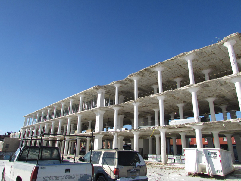
Figure 20. The demolition contractor did not take adequate precautions to ensure a uniform vertical demolition face along most of the eastern line of demolition.
However, along a majority of the eastern line of demolition at the northern SMI slab, the demolition contractor did not take adequate precautions to ensure a uniform vertical face of demolition across the depth of the slab, as shown in Figure 20. As a result, a number of top and bottom reinforcing hoops that were intended to remain were destroyed or damaged, as shown in Figure 21. As a result, and similar to that described at the large equipment access opening during the demolition Special Inspection, the load-carrying capacity of the remaining, immediately adjacent bays to the west of the line of demolition was reduced.
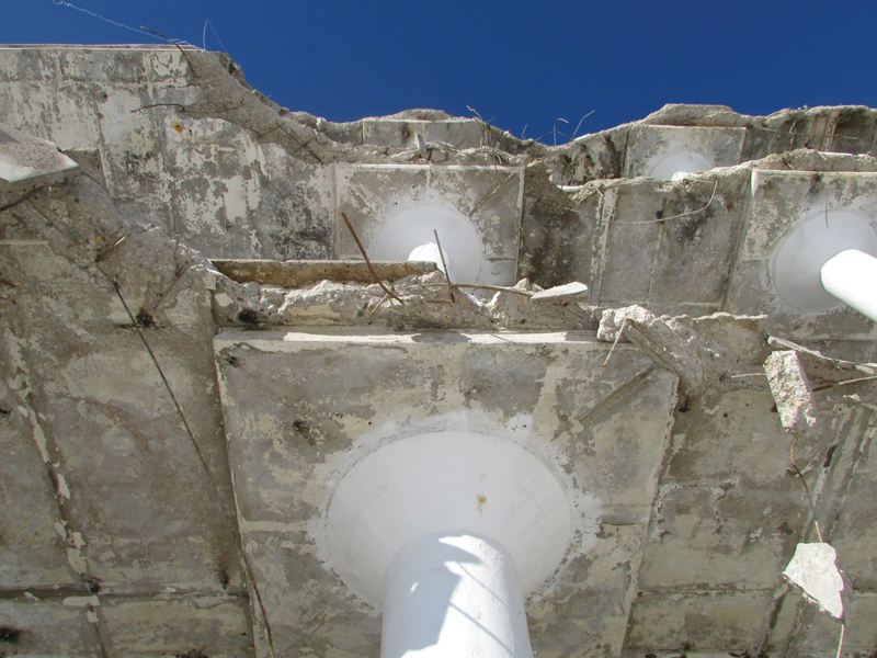
Figure 21. Several top and bottom reinforcing hoops that were intended to remain were destroyed or damaged, resulting in reduced load-carrying capacity of the remaining bays adjacent to the demolition line.
This reduction in load-carrying capacity occurred because once a hoop is no longer embedded in a significant portion of concrete anywhere along its circumference, or severed, it can no longer function to resist the radial flexural bending forces in the slab. Therefore, in an SMI slab when a top hoop is no longer able to function properly in response to negative cantilever flexural action induced by the supported adjacent simple span slabs, the undamaged diagonal and damaged orthogonal (i.e., north-south) positive moment span hoops must resist forces associated with a longer span because of the reduced effective cantilever distance of the Unit C section of the slab.
While the existing affected bottom hoops of the controlling diagonal span did appear to have enough reserve capacity to allow the slab to span the longer distance under its own dead load adequately, whether or not the slab had enough adequate reserve capacity to provide the required new adaptive reuse minimum live load of 40 psf and dead load of 15 psf for partitions, could not be confirmed. In addition, the load-carrying deficiency at the north-south orthogonal positive moment slab span was further adversely impacted by the loss of embedment or damage at some of the bottom hoops along the erratic line of demolition.
A proposed solution to the damaged conditions along the eastern line of demolition was submitted to Pennoni for review by another engineer engaged by the developer. The proposed solution involved attaching reinforcing bar dowels via mechanical couplers to all of the damaged reinforcing projecting from the line of demolition and encasing the same supplemental reinforcing in a newly formed and poured slab edge along the affected eastern edge of the northern section of the remaining building.
A review of the proposed repairs indicated that, for the framed SMI slab to be restored to its original capacity, the slab in the first bay west of the line of demolition would need to be jacked up to relieve all self-weight stresses from the remaining undamaged orthogonal and diagonal bottom and cantilever top hoops. Relieving the existing dead load from the remaining undamaged hoops would allow for the proper redistribution of the existing dead load to both the undamaged and repaired hoops, as well as ensure proper sharing of the proposed future loads by both the remaining and repaired hoops.
A plan of the required location of the temporary jack shoring was provided by Pennoni, which indicated that jacking of the slab to relieve the dead load must be sequential, starting at the ground level and then proceeding up to the next level above. The slab was to remain jacked up and shored until the repairs had been completed, and the new concrete slab edge had achieved full strength. Once the shoring was in place, the proposed couplers and bar extensions could then be added to the projecting remains of the top and bottom hoops so the same hoops could function again as initially intended.
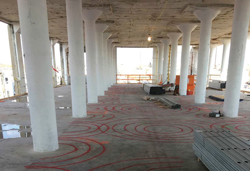
Figure 22. GPR equipment was used to locate the embedded SMI hoops, and their locations were painted on top of the concrete slab surfaces to prevent further damage.
After the completion of the demolition operation that involved drilling and coring new mechanical and utility penetrations, it was recommended that the location of the hoops be identified to prevent additional damage to all of the embedded and concealed SMI hoops during the renovation work. This was accomplished using ground-penetrating radar (GPR) equipment, which allowed for the location of the hoops to be painted on the surface of the concrete slabs, as shown in Figure 22.
Conclusion
As a result of the investigation associated with the adaptive reuse of the Apex Hosiery Company Building located in Philadelphia, a unique type of reinforced concrete flat slab construction, the SMI System, was encountered. The author had previously dealt with this type of construction at another building in Philadelphia. The findings of the investigation assisted with the successful completion of both the partial demolition of the existing structure and the success of the adaptive reuse project.■