
This is the first of a two-part article on repairing aging, normally reinforced, concrete garage structures existing in aggressive weather environments. The first article is from the perspective of the engineer and the second article from that of the contractor. While the topic is the same, and the articles are complementary, they are not intended to be a point-counterpoint.
The Designer’s Perspective
Although construction sophistication has improved remarkably over the years, there are many parking structures, particularly those in the northeast built forty to sixty years ago, that were constructed without much thought or understanding about how the aggressive nature of the environment and the world we live in would deteriorate these structures.
When one has been in the business of garage repair for a lengthy period, you encounter interesting situations and meet interesting people. This article is intended to be a useful tool for the younger engineer to be able to absorb some history and lots of experiences.
Parking garages come in many shapes, sizes, and structural configurations: Steel frame, pre-cast, CMU-bearing, metal-deck with concrete, post-tensioned decks (filigree-type), topped and pre-topped pre-cast, bituminous surface, free-standing garages, and garages beneath structures. This article will concentrate on normally reinforced, cast-in-place concrete parking structures.
A filigree concrete system consists of a relatively thin precast concrete panel that by itself is not sufficient to support full span line loads but, in composite combination with a cast-in-place topping, becomes a longer span, code load supporting structural floor or roof.
How does concrete in a garage structure deteriorate? Well-researched over the years, deterioration is largely due to the oxidation of the structural reinforcement which in turn creates a phenomenon called rust-jacking, resulting in spalled concrete. The rust-jacking phenomenon is evidenced in bulging and/or cracked concrete, often with rust staining, and is a direct result of the pressures created as embedded reinforcement rusts within the concrete structure. Low quality concrete, lack of air-retention, and concrete carbonation are all accelerants to the deterioration process.
A project usually starts when a facility user (usually the Owner) contacts the engineer or contractor stating that pieces of concrete are unusually erupting from the floor surface, exposing reinforcing rods, or falling from overhead. A quick inspection and a phone call advises the prospective client that water, making its way through or into the concrete, has been present around the reinforcement over a sufficient period of time to cause steel oxidation and the rust-jacking phenomenon. When the client asks what should be done, the response is typically: “Are you buying or selling?” That simply means does the client hold a long-term position in the facility, or are they simply looking to improve life-safety conditions in order to extend the service life for a short period? This article assumes that the prospective client is in a long-term position.
The garage study begins with a determination of the extent of deterioration. Spalling concrete on travel surfaces and on missing pieces from concrete soffits is readily observable. Beneath a surface that may visually appear to be secure could be an ongoing corrosion issue. Forty (40) years ago, a reliable process called “sounding” was utilized to estimate the extent of what was called “concealed deterioration”. Concealed deterioration suggests that the surface may appear to be sound or solid, yet the corrosion process beneath the surface has reached a degree where concrete has debonded or layered as a result of the rust-jacking process. Sounding requires nothing more sophisticated than a hammer, a steel rod, or a chain to be able to begin mapping the extent of debonding. Through the years, technology has developed some rather exotic means for determining the extent of debonding. Many an “older” engineer has noted that it would be great if someone would invent a way to assess debonding without the need to survey a surface on hands and knees while using a hammer. Technology has answered that request in the form of ultrasound, x-ray, or a rotary percussion tool on an extension pole. The newer techniques (still undergoing development for preciseness) are good for quantity mapping and relatively quick, general overviews. This author still finds that the precision of sounding is still the most reliable.
Sounding is best done in a relatively quiet environment so that the individual doing the sounding can hear the distinction between solid concrete (a clear ring) and spalled concrete (a dull thud). In a noisy environment, it is still possible to do sounding in a localized top of slab area, with a hammer, by lightly sprinkling small pieces of aggregate over the surface before sounding. The spalled concrete will vibrate, and a vibrating sand line demarking solid and debonded concrete can be easily observed. When marking for excavation, chalk or paint may be marked directly on the concrete surface. A good practice is to extend beyond the specific spall line by several inches to allow for oxidizing steel that may not yet have generated to the point of active spalling.
Concrete Removal
Electric or pneumatic chipping guns and hydro-demolition (hydro) are the tools of first choice for removing deteriorated concrete. Site conditions will often determine which method is the preferred technique. Hydro-demolition creates a significant amount of waste water that needs to be controlled. Although water-recovery systems and recycling can be utilized, there is still containment and waste water to be dealt with. One feature of hydro-demolition that mechanical demolition doesn’t provide is that hydro-demolition will often prepare the exposed reinforcement by removing oxidized material. Impact hammer is a more labor-intensive process and is a generator of airborne particles and greater airborne noise. Noise from impact tools and hydro equipment travels through a concrete frame for long distances. The hydro process overall creates less noise.
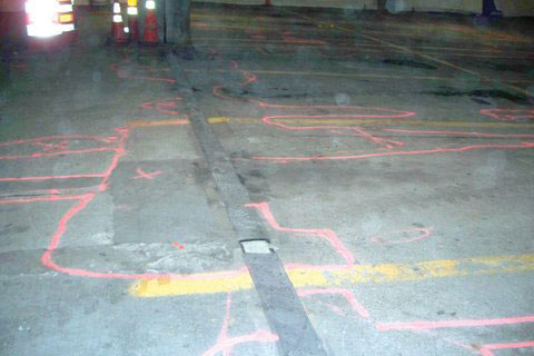
Figure 1
Once the sounding is done and the areas are marked out for excavation, the floor will probably look like an area of randomly located “amoebas” (Figure 1). In an ideal situation, isolated amoebas should be circular. In the case of concrete removal by pneumatic equipment, the easiest process from the contractor’s perspective, however, contains straight lines and large rectangles. Be mindful that extending well beyond the spall line removes sound concrete, where it will be more difficult to expose the encapsulated reinforcement that has not corroded. Leaving feathered excavation edges at concrete spall is a poor practice, and one that is almost guaranteed to result in lifting of the patch material at edges, even when a manufacturer of an engineered patching product permits feathering the edges.
Understanding a practical approach to concrete demolition requires an understanding of excavation equipment. If full demolition of concrete with embedded reinforcement is required, large impact equipment greater than 25 pounds could be appropriate. To retain solid concrete for patching, mid-size equipment to remove some of the most distressed concrete could be appropriate. Using smaller equipment, such as rivet busters and electric chipping hammers, for fine-tuning would be a next step. Detailed excavation utilizing hand-held hammers and cold chisels is appropriate. Removal of 2500 psi versus 6000 psi concrete will yield different experiences and require different techniques. Even though it may appear to be efficient, don’t use equipment that is larger than necessary, as there is an inherent danger of micro-cracking of concrete that is not intended to be removed.
Removing oxidation corrosion from reinforcing bars using wire wheels, hammers and chisels, sand blasting, and hydro-blasting can be appropriate. The engineer should also be mindful of evaluating the required structural strength. At times, the area/quantity of steel can be reduced and still satisfy the live load demand. As an example, a specification that reads “steel with a 10% cross-section reduction is to be supplemented” might be an unnecessary regiment if the existing steel could satisfy the intended design purpose with a cross-section reduction of 25%.
Why is it often suggested to have more cover protection for the reinforcement that is to remain in the repair area than was necessary during the original construction? In a final product where a parking garage will receive an opaque elastomeric waterproof coating, a typical recommendation, the conditions that promoted the original deterioration will be largely controlled. With a system that will remain uncoated, wisdom suggests that more attention should be paid to the protection of the reinforcement. Protecting the reinforcement in the patch area reduces the corrosion potential for that steel, but forces the corrosion potential to the unprotected steel that is adjacent to or entering the patch area. This often gives rise to a phenomenon called the “halo-effect”, where the patch appears to be working well, yet through the years the adjacent concrete begins to deteriorate. Surrounding the perimeter of the patch area with sacrificial anodic devices will prolong the life of the original reinforcement adjacent to the patch and is a great technological advancement. There are several manufacturers who will provide devices for this particular purpose. Vector Corrosion Technologies has been responsive in assisting the author’s firm with technical support in this respect.
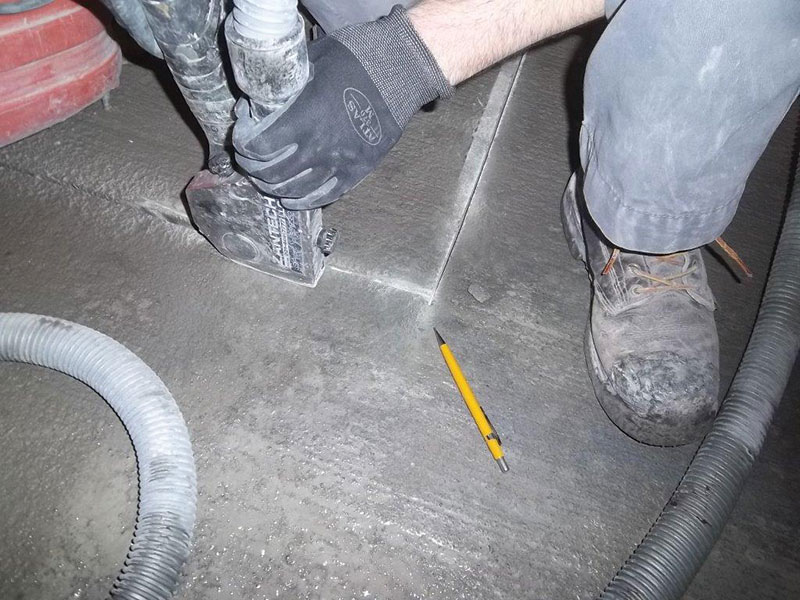
Figure 2. Grinder with vacuum attachment.
Parent Concrete to Patch Interface
There are several possibilities to address the interface between new and existing concrete. For the feather edge spall, a definite demarcation is necessary. A logical approach is to make a saw/grind cut, which is often restricted to a ¾-inch depth. Three-quarters of an inch is a reasonable cut depth, or estimation of the clear cover, so as to maintain intact the existing steel beyond. Confirm this dimension before production cutting. Increasing the depth beyond ¾ inch using impact power tools will result in a rough surface, which is desirable to promote bond between the existing concrete and new patch material. Grinding/cutting will appear to polish the cut surface of the sound concrete. For bonding purposes, this is a poor surface. If using grit blasting to clean the reinforcing steel, one can utilize that same process to provide a light raised profile to the cut surface. A natural hair-line shrinkage crack is likely to form at the patch-to-parent concrete surface, resulting from concrete shrinkage while curing. It is almost impossible to eliminate this crack, but control of water content and good construction practices are very helpful in minimizing it. Again, understanding if the final product will receive an opaque coating will assist in these decisions. The meeting line of new patch material to old concrete is one of the more vulnerable locations when considering crack control. It is the location where essentially dissimilar materials come together and results in a natural shrinkage line. If the final product does not receive a topical waterproof coating, one can be assured that some level of deterioration will initiate at this location. If the patch material and the parent concrete begin to debond at this location, having a slight undercut of three to five degrees on the ground joint will provide a mechanical wedge, which will help to control the patch from lifting. The rough profile of a grit blasted joint (adequate) or a mechanically profiled surface (best) to create a friction interface can be very beneficial. A minimum ¼-inch amplitude profile on the horizontal surface of the patch area has been found by the author to work well.
Bonding the patch material to the parent concrete is the greater challenge and may be where the success of the patch is ultimately judged. The reader may have heard statements to the effect that the process of curing concrete is never completed. The author read in one article that concrete used by the Romans is still in the process of hydrating. Taking advantage of cement particles within the parent concrete that have been relatively dormant and can participate in the hydration process can be done by achieving a saturated-surface-dry (SSD) surface. From the author’s perspective, this means more than simply applying a light water spray to the surface immediately before patching; it means providing a 12-hour saturation by first applying the water spray and then covering with burlap/burlene/etc. to prevent drying. Without letting the surface dry, and immediately before applying the patch material, apply a coating of neat cement (cement mixed with water to the consistency of heavy paint) to the SSD concrete surface. Take the time to broom the neat cement into the parent concrete and a perfect surface will be readied for bonding the new to the old concrete. Do not let the neat coating dry, otherwise a surface of dry, dehydrated cement will result and the bond will be negatively impacted.
The placement of concrete is one that requires attention by both consultant/inspector and contractor. Apply the neat cement in advance of the concrete placement so that it is not permitted to dry out. A color change in the neat from a dark gray sheen to a light gray mat color is an indication that drying has taken place. Drying does not mean that the cement in the neat has cured. In drying out, it becomes a bond-break surface that may not regenerate during the hydration process. In the early stages of the drying process, if the concrete is delayed in delivery, a light spray from a hose is acceptable. The light spray should not be of a concentration that allows water pockets to accumulate. With longer delay, applying additional neat and brooming it vigorously will break up the surface that has begun to dry, and allow it to be reestablished. One can probably get away with doing this once. Beyond that, the surface is lost and grit blast removal of the dry neat is recommended.
Generally, spalls are a rather shallow patch, which makes vibrating of the concrete for consolidation purposes difficult. The use of pencil vibrators can be very helpful, particularly where there are significant areas of reinforcement congestion. A relatively new tool called the vibrating screed, that can be operated by one person, has been found to be very beneficial for concrete consolidation as well as surface profile/finish.
The contractor and inspector should not be the decision makers as to: (a) how aggressive the concrete removal is, (b) how much of the bar is to be exposed, (c) is there excess steel which may be removed, or (d) where and how much shoring should be placed. These are questions for the Engineer of Record.
Working the edges of a patch placement to consolidate the concrete against the parent substrate is a very important step. Finishing the concrete surface to prepare it for either vehicle traffic or for subsequent coating is an important step as well. Be familiar with the use of the garage to determine whether an aggressive or a lighter broom finish is required. If the garage is to be coated, a magnesium float surface is perfectly acceptable.
Facilitating the curing of the patch material takes place either with the application of moist curing blankets or chemical spray-on compounds. If using a chemical and the garage is to be coated, don’t use a chemical that will not be removed with the track blasting process.
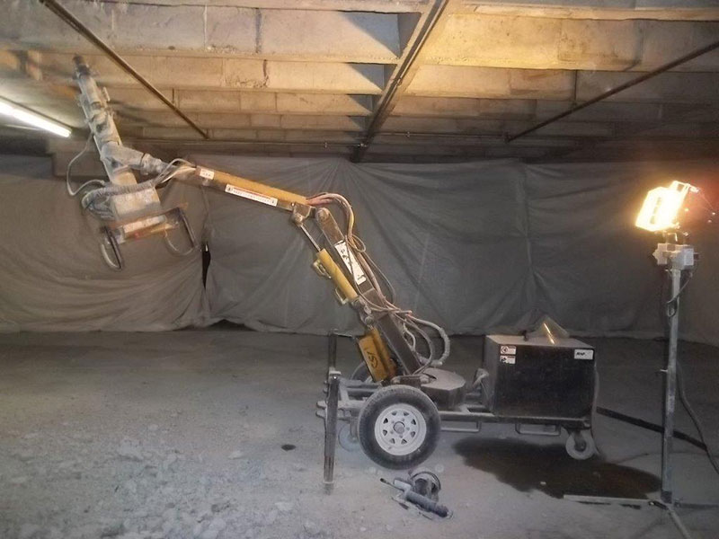
Figure 3. Remotely operated excavation hammer.
Soffit Repair
Repairs on vertical surfaces and overhead repairs require different techniques altogether. First, one needs to assess what has been the contributor to the overhead spalling and steel deterioration. Has the deterioration resulted primarily from the passage of water from above, or are other issues involved? One will probably find the largest extended deterioration results from cracks in the concrete that allow aggressive water to pass through. When a garage ages and when it has been exposed to the carbon-monoxide rich environment of a parking garage, carbonation of the concrete can take place. This process dilutes the natural passivity protection that concrete provides to the steel, thereby creating increased corrosion potential. Those practicing in New England, repairing garages along the coast, are faced with an unusual situation in garage repair. Carbonation, chloride-laden air, and seasonal condensation cycles (Spring/Fall) initiate steel corrosion and concrete spalls on concrete garage surfaces of the underside of decks that have no other explanation.
Overhead Repair
Overhead work can be as demanding as deck work. Almost exclusively today, overhead patching is done with a combination of hand-patch materials, hand-patch and partial form work, or overhead pumping with engineered materials. With the exception of rare instances where traditional sand and cement dry-pack is utilized, prepackaged engineering products produced by a variety of manufacturers are used today. Those products with a cement base are ones with which the author has had the most success. With the hand-patch process, the construction crew is usually unable to proceed the placement with repeated misting of the parent surface and neat application. Here is where one faces the engineers’ conundrum. If everything noted in this discussion is necessary to achieve a good patch with long term viability, how can the engineer accept something less? The realities are quite simple. The “old fashioned” process of hand patch with cement-sand-and-water, followed by asking the facility operator to keep traffic off the surface above the patch for at least fourteen days to control vibration that would de-bond the patch, is not a dying process…it is “dead”. Here is a suggestion: knowing that overhead patches are questionable, should something go wrong and a potentially hazardous situation result from the overhead patch material dislodging, the author’s firm utilizes a combination of the existing rebar and non-corrosive pins and wires within the patch material to provide secondary securement of the new material.
Soffit forming and patch material placement by pumping has advanced substantially over the last 10 to 15 years. The need to over-pour through a pour pocket or trough to create a concrete head has been largely done away with, with flow-able materials [shrinkage compensated] and pressure pumps. Creating an SSD surface is much more difficult overhead. Young engineers should not despair. As self-consolidating concrete (SCC) has allowed the engineer to design a w/c = 0.4 concrete, water reducing admixtures have allowed that design to be placed with a 9-inch slump, a magic “goo” results that can provide confidence for long-term bond of patch material to parent concrete. Just wait and see!▪