A Case Study
Structural Insulated Panels (SIPs) have historically been used more for residential construction than for non-residential construction. However, SIPs are gaining popularity in the commercial arena, especially for school construction. There are several schools throughout the country that have incorporated SIPs. One such school is Silvis Middle School in Silvis (East Moline), IL. This 52,600 square-foot facility was designed with SIP roof panels over metal bar joists, steel beams, and steel columns. SIPs were also used for the exterior walls, creating a full SIP building envelope. It is often assumed that SIP construction is more expensive than other construction methods. However, one of the reasons that SIPs were selected as the method of construction for the Silvis Middle School project was because they were the least expensive of the options that were being considered for the exterior walls.
The Role of the SIP Engineer
Structural Insulated Panels are a pre-engineered building component, similar to pre-engineered wood trusses. SIP manufacturers produce SIP shop drawings, which are then reviewed by the project design team. On non-residential projects (and some residential projects), these shop drawings must be stamped by a PE licensed in the state where the project occurs. The SIP engineer reviews panel thicknesses, panel spans, connections, etc. The main difference between SIPs and wood trusses is that SIP span charts and load tables are typically based on testing, rather than material properties and calculations. Most SIP manufacturers have a code listing through ICC or an independent testing company. The manufacturer’s code listing will typically include an axial load table for wall panels and transverse load tables that would apply to wall, floor, and roof panels. There is also usually a shear wall capacity indicated, which is sometimes referred to as a “racking shear” capacity. The role of the SIP engineer is to compare the code-required design loads to the allowable loads in the code listing. Adjustments are then made, as required, to insure that the structure can resist the required design loads.
Like any other pre-engineered system, there is a line between what is designed by the specialty engineer and what is designed by the engineer of record. This line can become blurred at times, especially on a project where the architect and/or engineer of record are not familiar with structural insulated panels. It is important to identify the scope of work of the specialty engineer (SIP engineer) up front, in order to avoid overlap or gaps in the structural design on the project. Ideally, the SIP engineer would only be responsible for the component loads that apply directly to the SIP panels, and not to the global loads that apply to the building as a whole. However, some of these global loads (like shear wall loads) might be calculated by the engineer of record and given to the SIP engineer to check against the capacity of the SIPs.
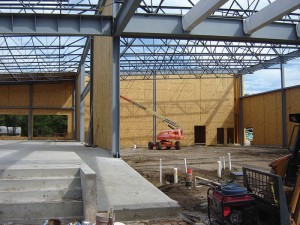
SIP wall panels go up first, followed by the roof panels, providing a strong, well-insulated building enclosure.
A Diaphragm is a Diaphragm is a Diaphragm
One structural element that is present on most buildings is a diaphragm. SIP structures are no different. Every SIP roof will act as a roof diaphragm. The challenge is that most SIP manufacturers do not have specific allowable diaphragm values indicated in their code listing. The main reason for this is that they have not had specific ASTM diaphragm testing performed on their panels. The allowable “racking shear” values indicated in some manufacturers’ literature are often used when checking both shear walls and diaphragms. This is a valid approach, but it’s not quite as simple as just comparing the numbers. All shear walls and diaphragms have chord forces that must be accounted for in the design, and this applies to SIP structures too. Fortunately, most SIP shear walls have continuous wood studs embedded in the ends of the panels, and they serve as the chords at the ends of shear walls. Hold down anchors are attached to the bottom of those studs to resist overturning forces, where applicable. The top and bottom plates of each shear wall will also serve as chord elements, and those plates need to be able to resist the chord forces as well.
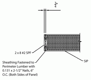
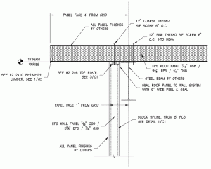
Roof diaphragms are typically much larger than shear walls, which can be a blessing and a curse. The benefit is that diaphragm forces are resisted along the full length of the perimeter walls or other lateral force resisting elements. The challenge is that the wood 2x members that are embedded in the edges of the roof panels will not be continuous, making it necessary to check/design the joints for the chord forces. In addition, attachment of the diaphragm to the structure below must be designed just like any other diaphragm. On the Silvis Middle School project, the SIP manufacturer was required to have diaphragm testing performed on their panels in order to satisfy the project design team. As a result, diaphragm test reports were available, which included specific edge conditions that were used during the testing process. See Figures 1 and 2 for details of the edge conditions that applied to the perimeter of the roof diaphragms on that project. These sections were taken from the diaphragm test reports, and they were included as part of the SIP shop drawings for the project. Section 3-3 shows metal straps being used to transfer tension chord forces across a joint in the 2x members embedded in the perimeter of the roof panels.
If the roof diaphragm had consisted of metal roof deck over steel framing, the roof diaphragm forces would have been compared to allowable diaphragm capacities published in the metal deck manufacturer’s literature. Those allowable diaphragm capacities would fluctuate, depending on the spacing between fasteners at the edges of the deck. Metal deck diaphragms have a higher capacity when they are attached to the structure more frequently, and when they have more fasteners at the joints between sheets. SIP roof diaphragms are no different. The diaphragm testing was performed on SIP roof panels with edge and joint fasteners spaced at 6, 4, and 2 inches on-center. The results indicated that SIP diaphragms have higher capacities when the fasteners are spaced closer together. Therefore, the general concept of designing a SIP diaphragm is really no different than designing diaphragms of other materials. The Structural Insulated Panel Association (SIPA) has purchased the diaphragm test results from the SIP manufacturer for the Silvis Middle School project, and those results will be made available to other SIP manufacturers that are SIPA members. This will go a long way toward allowing the use of SIPs on other non-residential projects, particularly by SIP manufacturers that have previously never had diaphragm test reports that they could use.
Do the Details Match the Design Intent?
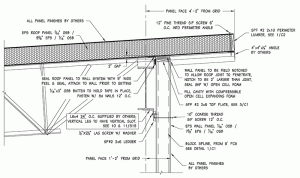
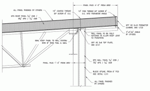
On the Silvis Middle School project, the SIP roof panels were supported by steel bar joists and steel beams. The lateral force resisting system for the building consisted of a combination of steel braced frames and steel moment frames. Design engineers asked if the SIP wall panels were intended to take axial load from the roof panels, and were told that they were not. They also asked if the wall panels were intended to act as shear walls, and were told that they were not. The wall panels were intended to resist transverse wind loads only, and they were not to be designed for any other loads. On the project drawings, the SIP roof panels were shown being attached directly to the top of the SIP walls, which were located immediately adjacent to the perimeter line of framing. Since the bottom of the roof panels were shown in direct contact with the top of the wall panels, the steel framing could not deflect without imposing axial load into the wall panels. In addition, the direct attachment of the roof panels to the wall panels would not allow the steel moment frames to “drift” without imposing shear load into the wall panels. Since the details were not consistent with the design intent, the design engineers suggested changes to the detailing. In order for the steel roof framing to deflect without applying load to the top of the wall panels, a 2-inch gap was created between the top of the wall panels and the bottom of the roof panels. This gap was then filled with compressible foam to complete the building envelope (Figures 3 and 4).
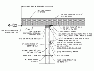
Allowing the steel moment frames to drift without applying shear loads to the wall panels was a much more challenging task. The tricky part was that the wall panels still had to resist transverse wind loads, but they could not be directly attached to the roof panels. The solution was to provide a slotted connection that would allow movement in the direction parallel to the wall, but that would resist movement in the direction perpendicular to the wall. Since the perimeter line of steel framing was adjacent to the wall panels, this connection had to be made at the bottom of the steel beams, for accessibility reasons. The connection could not be made at the top of the beams, because there was no access to the fastener once the walls were in place (Figures 5 and 6).
Conclusions
Structural Insulated Panels (SIPs) can be used on non-residential structures, as well as residential structures. Many of the design challenges that designers face when designing with SIPs are no different than when designing with other materials. The general concepts of structural design still apply when designing with SIPs – complete load paths, applied loads must not exceed allowable loads, detailing must be consistent with design intent, etc. SIP manufacturers and SIP engineers typically have a lot of experience and knowledge with regards to designing and building with SIPs. Design teams should not be afraid to tap into that knowledge and experience.▪
This article was previously published in the Wood Design Focus, Spring 2012. It is reprinted with permission.


