
The design of the roof of the recently completed La Plata football stadium represents a serendipitous merging of two concepts: the award winning competition entry by the architect, Roberto Ferreira, and the Tenstar Dome™ structure originally developed by Weidlinger Associates for the Georgia Dome. Compared to the Georgia Dome, however, the La Plata project presented some unique engineering challenges. Instead of having a continuous oval perimeter, the plan of La Plata is based on two circles 279 feet (85 meters) in diameter whose centers are separated by 157 feet (48 meters), resulting in a configuration that looks like a MasterCard® symbol (Figure 1).
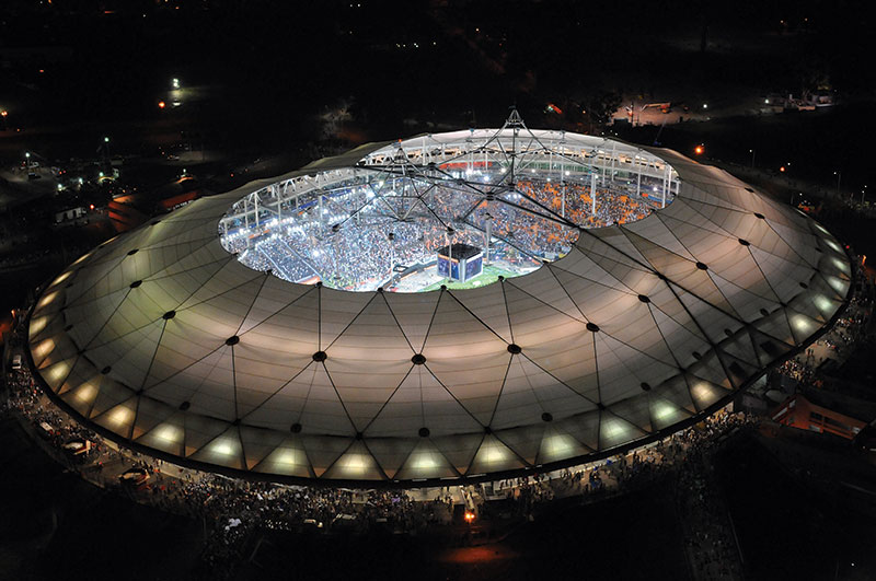
Figure 1: Aerial view of completed stadium showing figure-eight-shaped opening.
Furthermore, the requirement for natural ventilation resulted in the need for openings at the two peaks, 222 feet (67.6 meters) above the playing field, defined by the center of the two circles and protected from rain by umbrellas, affectionately called “sombreros.” Finally, a compression ring around the arena, instead of being built of concrete as at the Georgia Dome, was conceived of and built as a triangular steel truss, partly to introduce lightness in what is a very massive structure, to encourage free airflow in this naturally ventilated dome, and to provide space for two levels of skyboxes and control booths.
The 53,000-seat soccer stadium in La Plata, Argentina, opened in 2003, lacking its signature twin-peaked fabric dome, and reopened to great fanfare on February 17, 2011, after completion of its roof structure, which was two thirds covered. Construction of the first phase of the project started in 1998, resulting in the completion of the playing field somewhat below original grade and an earth berm on which was poured a concrete seating bowl, crowned by the trussed steel compression ring. The material for the roof, including the fabric and cables for the Tenstar Dome, was also purchased at that time and placed in storage when Argentina faced a financial crisis in 2000. For the next 11 years, the stadium, with its trussed compression ring in place, stood waiting for construction of the roof.
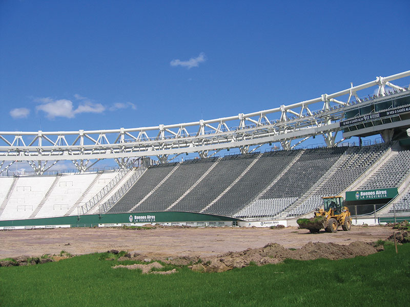
Figure 2: Interior view of compression ring.
The trussed compression ring (Figure 2) consists of steel pipes with diameters of 42 inches (1,066 millimeters) for the top chord, 36 inches (914 millimeters) for the posts, and 28 inches (711 millimeters) and 18 inches (457 millimeters) for the diagonals. The vertical posts of this truss form a colonnaded gallery at the back of the stands and sit on baseplates anchored to the foundation which consists of concrete pile caps at the top of the berm, with concrete piles that extend down to virgin soil. Concrete grade beams tie the pile caps together and act essentially as the bottom chord of the trussed compression ring. Since the compression ring must carry both gravity loads from the roof and wind loads acting against the roof surfaces, lateral resistance is required between the ring and the foundations. The roof structure is also subject to thermal stresses due to temperature variations resulting from restraining the ring at the foundation. These were analyzed and were found to be acceptable if one post on each side of the kink (where the two circles meet) was radially released. This was accomplished with guided Teflon® bearings that permit radial displacement but not circumferential movement. Framing for the skyboxes and control booths was set into and hung from the 42.6-foot (13 meters) high and 29.5-foot (9 meters) wide trussed compression ring.
The vertical posts were shop fabricated with gusset plates to catch diagonal and radial tubes. At the top of each post, a gusset plate was provided to engage the socket of the cable dome’s radial cables and fitted with holes through which temporary construction cables could be connected. Since the circumferential top chord pipe is always in compression, flanged, bolted connections were installed at the top of the posts. The truss diagonals are either bolted or pinned to the joint weldments.
The top of the posts form the spring line for the dome, which consists of the triangulated ridgenet of cables characteristic of a Tenstar Dome. A series of three tension hoops step inward and upward from this inner top chord of the truss. Cables sloping down from the top of the posts hold the first of these hoops. From the node formed by the intersection of these sloping cables and the first tension hoop, a rigid vertical post, called a “flying post,” rises to the first line of ridgenet nodes. From those nodes, diagonal cables slope down to the second tension ring, which supports a second series of posts. This sequence is repeated until reaching the top of the third ring, at which point another series of cables converges at the center of each peak. Catwalks are attached to each hoop cable, and bridges interconnect the catwalks for access to the lighting and sound systems and rigging for special events (Figure 3).
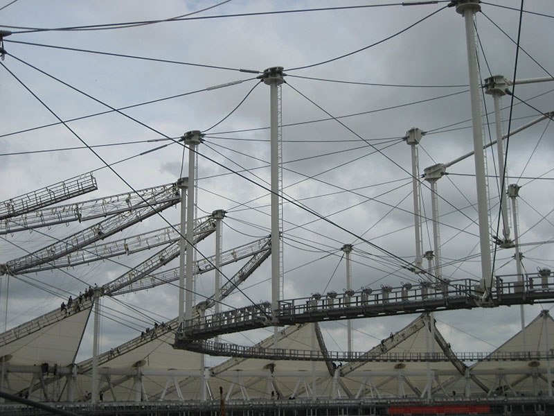
Figure 3: Interior view during construction, showing catwalk on bottom hoop cable and ridge cables at top nodes.
Because of the kink at the center of the stadium that results from the reentrant perimeter, the members along the centerline are subject to compression rather than tension and are therefore pipes rather than cables. This introduced a complication in the erection of the dome and the need for added temporary towers. It also necessitated a field modification to the nodes at the top of the posts in the region of the kink to permit both radial and transverse rotation.
The nodes at the top and bottom of each of the flying posts are unique weldments that have to accommodate the continuous tension hoop cables and diagonal cables, as well as attach to the post itself (Figure 4). The hoop cables that continue through the node sit in a slot formed by steel bars welded to a steel plate. They are clamped down with a second plate that is bolted to the first, creating a friction clamp. Since as many as four 3.9-inch (98-millimeter) cables are used in the first hoop, the resulting welded steel node assemblies are very large, with overall dimensions of 6.6 feet (2 meters) x 6.6 feet (2 meters) x 3.3 feet (1 meter) and weighing as much as 2 tons. The top weldment, with gusset plates for ridge cables and diagonal cables, is rigidly attached to the post, while the bottom weldment is pinned, permitting radial rotation.
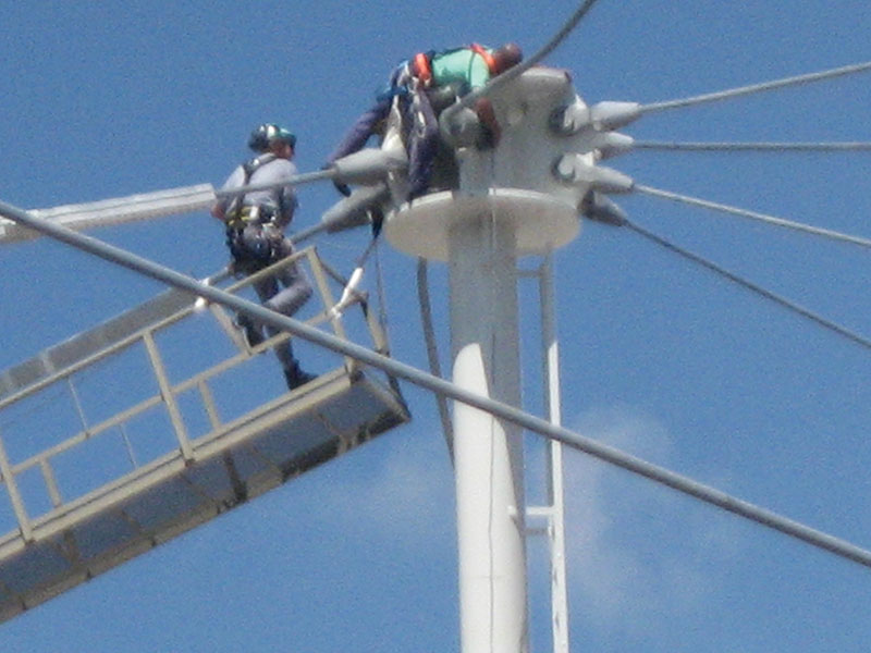
Figure 4: Attachment of cables to post.
The Tenstar Dome is a tensegrity system that is defined as a “spatial network in a state of self stress.” The system acts like a truss in which the bottom chord is interrupted and follows the line of hoop cables around to the opposite side of the arena. The system is truly three-dimensional rather than planar, and therefore benefits from the triangularization of the structural elements. This improves load-carrying capability and permits the unconventional geometry of structures such as La Plata. To prevent cables from becoming slack under load, the system has to be prestressed, resulting in an extremely rigid structure. Instead of providing a means of adjusting the tension in each cable, in a Tenstar Dome such as La Plata, lengths are fixed based on the final configuration of the dome and the level of prestressing needed. This implies that the system remains slack until the last cable or post is installed, and therefore impacts the erection system.
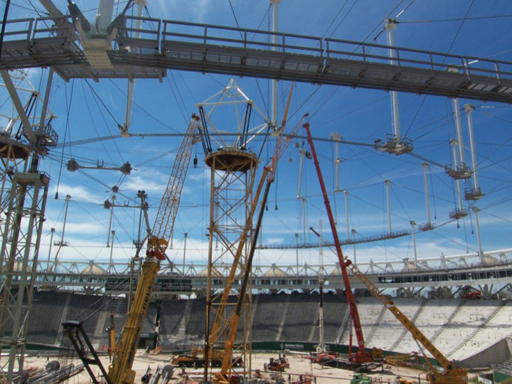
Figure 5: Temporary erection tower.
Two temporary towers were built to erect the roof structure, one at the center of each of the two peaks (Figure 5). Jacking cables from these towers were run through sheave blocks (pulley devices) at each node of the assembled hoops, laid out on the ground, and run through another set of sheave blocks at the top of the ring, which were in turn connected back down to the hoops. This arrangement lifted the hoop simultaneously upward and outward into its final position, where it could be connected to the diagonal cables. To create the kink, a temporary cable was stretched across the stadium, connecting the two sides of the hoop cable. The vertical posts were then lifted into place and attached to the nodes in the hoop cable. Afterwards, the ridge cables were attached to the top of the posts. This same procedure was followed to the center of each peak. During the erection of the rigid members comprising the elements across the kink at the centerline of the stadium, secondary temporary towers supported the arch structure. Also, since the compression ring tends to move inward when the cable net is installed prior to the completion of the arch structure, a telescoping vertical member was provided at the center of the arch and was jacked once the structure was completely assembled, in order to move the ring back out to its final location.
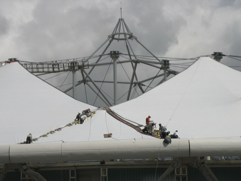
Figure 6: Installation of fabric cover over cable network.
Once the cable network was complete, the fabric covering was installed (Figure 6). The special fabric used on this project is a high-translucency Teflon-coated fiberglass that was developed to provide sufficient natural light for growing the turf. Although studies demonstrated the fabric’s effectiveness, the owners were concerned about the damage to the turf that would occur when the arena is used for special event such as concerts. Therefore, it was decided to pave the playing area and to use palletized grass panels that could be stored outside the stadium when not needed for soccer games. This solution helped make La Plata Stadium a truly multipurpose arena.
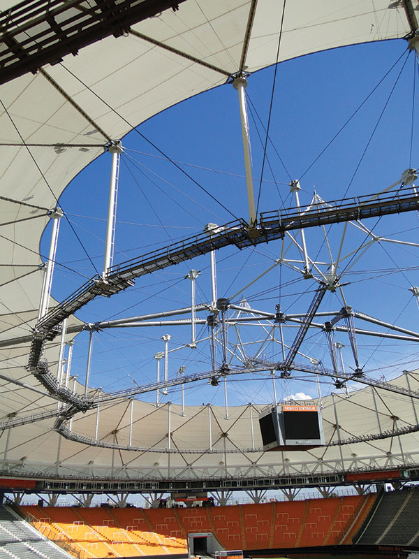
Figure 7: Interior view of completed roof.
This phase of the roof construction extended the fabric only to the second hoop, leaving a figure-eight hole in the center of the stadium. (Figure 7). However, the Tenstar cable dome structure is currently complete, and when the balance of the fabric and its two sombreros are added, the architect’s original conception will finally be realized.
The construction of the La Plata dome recognizes the adaptability of the Tenstar concept to complicated shapes that can be built in stages to meet owners’ financing constraints. Variants of this concept are currently on the drawing boards, including a retractable roof that rides on top of the cable dome, providing a lightweight, aesthetically pleasing yet economical solution for covered arenas.▪
Materials
Cables: 500 tons
Steel compression ring: 3,000 tons
Skyboxes: 1,000 tons
Posts, Arch pipes, Central pentagons: 800 tons
Weldments, catwalks: 600 tons
UltraLUX fabric: 29,300 square meters (315,268 square feet) and 27 tons
The Team
Engineer: Weidlinger Associates, Inc., New York, NY
Architect: Roberto Ferreira, Arquitectos, Barcelona, Spain
Roof Contractor: Birdair, Inc., Buffalo, NY
Steel fabricator: Astillero Rio Santiago, Ensenada, Argentina
Cable supplier: Wire Rope, Montreal, Canada
Software: LARSA and MCM/BLD3D