Bridges across the country are deteriorating or becoming functionally obsolete. Therefore, Departments of Transportation (DOTs) across the country have to identify and save historic bridges, thereby streamlining the replacement of non-historic bridges. The Minnesota Department of Transportation (MnDOT) identified the Holmes Street Bridge (Bridge No. 4175), commonly referred to as the Shakopee Truss Bridge, as one of 24 bridges in Minnesota to preserve once funding became available. For the Holmes Street Bridge, funding became available with passage of the American Recovery and Reinvestment Act (ARRA) of 2009.
The project team of HDR as the Bridge Engineer and Mead & Hunt as the Project Historian faced many challenges. The first was the need to complete not only the inspection, analysis and rehabilitation report in six months, but also receive approval on final rehabilitation plans and specifications from MnDOT, the State Historic Preservation Office (SHPO) and the Federal Highway Administration (FHWA). A similar project would normally take 12 to 18 months.
The next challenge was to identify engineering solutions that would meet safety and maintenance requirements, while preserving the historic features of the bridge. The inspection and analysis revealed the bridge to be in generally poor condition, with severe to critical deterioration in various steel and concrete members. Innovative design solutions that preserved the historical significance of the bridge included replacement of the existing ornamental railing in-kind with a safety modification, installation of replica lighting, replacement of some truss members and steel overhang brackets with shop fabricated members using rivets, and rehabilitation of concrete components using unique renovation techniques.
Bridge Description
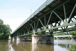
The Holmes Street Bridge, built as a highway bridge in 1927, provided access across the Minnesota River for the city of Shakopee and points west to the Twin Cities Metro Area. Listed in the National Register of Historic Places (National Register) as a rare example of a deck-truss bridge in Minnesota, the Holmes Street Bridge is a 645-foot long bridge with an out-to-out width of 42.4 feet. The superstructure consists of two 30-foot long cast-in-place reinforced concrete deck girder south approach spans, four 125-foot long riveted steel deck truss main spans, and two 30-foot long cast-in-place reinforced concrete deck girder north approach spans. The truss spans consist of three parallel riveted steel Warren trusses with verticals. The bridge deck consists of a 30-foot wide roadway and two 6-foot wide raised cantilever sidewalks.
The substructure consists of a U-shaped reinforced concrete South Abutment, two reinforced concrete south approach piers with four arched openings, three reinforced concrete river piers with two recessed arches on each side, two reinforced concrete north approach piers with four arched openings, and a U-shaped reinforced concrete North Abutment that features a stairway on the east side.
In order for a property to be historic, it has to have character-defining features which are prominent or distinctive aspects, qualities, or characteristics that contribute significantly to its physical character. Features may include materials, engineering design, and structural and decorative details. The Shakopee Truss Bridge has two character-defining features which were defined as follows in the MnDOT Historic Bridge Management Plan for Bridge No. 4175 (June 2006):
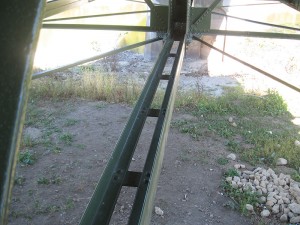
- Feature 1, Deck-truss design and construction. The Shakopee Truss Bridge is a rare example of a deck truss bridge in Minnesota. This feature includes the four main spans, each of which has three riveted, steel trusses designed in a Warren-with-verticals configuration.
- Feature 2, Classical Revival architectural details. Because of its urban location as a gateway to downtown Shakopee, the Shakopee Truss Bridge was designed with Classical Revival stylistic elements. This feature includes recessed panels in the concrete river piers (Piers 3-5), open-arched concrete piers in the approach spans (Piers 1-2 and 6-7), recessed panels on the abutments, ornamental metal railings on the approach spans and main spans, concrete parapet railings on the abutments, and stairways adjacent to the north abutment.
In-Depth Inspection and Analysis
The project team performed an in-depth inspection of the bridge from within arm’s length of each member. Access to inspect the bridge truss members was provided from an Under Bridge Inspection Vehicle (UBIV) with a 60-foot reach.
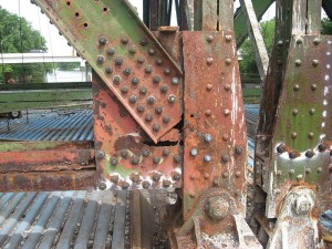
The in-depth inspection revealed delaminating and spalling concrete members; severely corroded ornamental railing members; severely corroded sections of stringers, floor beams and overhang brackets; severely corroded truss members; gusset plate section loss; pack rust; and frozen bearings. Most of the deterioration of the steel members was located in areas that were exposed to moisture, namely the exterior trusses on either side of the bridge and areas adjacent to the open joint at the end of each truss span.
LARSA and STAAD 2D truss models were created to determine the forces in the various truss members. Prior to the project, it was determined that, following rehabilitation, the bridge would be reopened as a pedestrian and bicycle bridge with vehicles using a new bridge constructed downstream. Therefore, the bridge deck was analyzed using the controlling load case between an 85 psf pedestrian live load or an American Association of State Highway and Transportation Officials (AASHTO) standard H-10 Design Truck which consists of 4 kip front axles and 16 kip rear axles separated by 14 feet. The raised sidewalk was analyzed using only the 85 psf pedestrian live load. A special load case consisting of the UBIV was also considered, as this would be the vehicle used to inspect the bridge. The analysis followed the AASHTO Manual for Bridge Evaluation and the MnDOT LRFD Bridge Design Manual.
The analysis models coupled with spreadsheets developed by the project team to analyze gusset plates, and information from the in-depth inspection, revealed which portions of the bridge needed to be repaired or replaced. This included gusset plates, floor beams, stringers, overhang brackets, and truss members; the raised concrete sidewalks; the roadway deck; expansion joints; bearing pins; the ornamental metal railing; and concrete surfaces.
Repair Recommendations and Innovative Solutions
As the bridge was historic, the project team had to ensure that the rehabilitation plans on this eight-span concrete girder and steel deck truss structure complied with Section 106 of the National Historic Preservation Act, and followed guidelines in the National Park Service Preservation Brief 15, Preservation of Historic Concrete. Additionally, the project could have no adverse effects on the historic resource as determined by MnDOT, SHPO and FHWA.
To streamline the process of determining the appropriate treatment methods for the extensive concrete repairs, the project team developed a repair matrix that distinguished treatments based on location and public visibility. For example, the team determined that concrete areas not visible, such as river pier areas, could be repaired with standard MnDOT construction techniques. Areas clearly visible to the public, including abutments and parapets, required historic repair techniques to ensure conformance with historic surfaces, and were included in the detailed project specific specifications. The specifications included requirements that the repaired concrete match the adjacent existing concrete in terms of finish, texture, surface detail and color. The contractor was required to provide a minimum of 3 samples, at least 12 inches by 12 inches in size, to demonstrate that they could match the adjacent existing concrete. The matrix clarified and expedited the appropriate treatments for both plan development and communication with the contractor.
An additional repair matrix was developed to address the repair and/or replacement of deteriorated steel truss members.
Rivets are a key feature of historic truss members, but few contractors today are able to install rivets in the field. When 30 steel sidewalk overhang brackets and six bottom chord members in highly visible areas were severely deteriorated and required replacement, the project team specified that the new members be shop-fabricated with rivets.
Historic railing typically presents design challenges due to noncompliance with current safety standards. The original metal ornamental railing was no exception. Not only did the railing openings not meet current MnDOT or AASHTO standards, but multiple sections exhibited critical deterioration. The project team looked at six different options ranging from reuse to replication to redesign, but based on issues of deterioration, cost and safety, the team chose to replicate the original railings with minor modifications, while refurbishing original castiron newel posts. AASHTO standards require that openings between members of pedestrian railing shall not allow a 6-inch sphere to pass through the lower 27 inches of the railing and an 8-inch sphere should not pass through openings above 27 inches. MnDOT standards, which are more stringent than AASHTO, require that openings between members shall not allow a 4-inch sphere to pass through the lower 27 inches, and a 6-inch sphere should not pass through any opening above 27 inches. The original railing allowed a 6-inch sphere to pass through openings both below and above 27 inches.
Therefore, MnDOT issued a design exception for the project, whereby the MnDOT requirements for the openings in a pedestrian railing were waived in favor of the AASHTO requirements. The replica railing was able to meet AASHTO opening requirements by the addition of a 3/16-inch steel stainless steel cable, which prevented a 6-inch sphere from passing through the lower 27 inches of the railing. It was determined that the addition of the stainless steel cable was less intrusive on the character-defining feature, than changing the dimensions of the railing to meet today’s design standards. To reduce cost, the team recommended button-head bolts with acorn-style nuts replicate the 1,200-plus rivet connections of the original railing.
Another innovation related to historic truss members was a solution to prevent future deterioration, most of which was due to drainage runoff from the deck drains and open joints at each truss end. Hydraulic analysis showed that the deck drains could be eliminated, and the open joints could be replaced with strip seal expansion joints. This was a simple and ingenious solution to damaging deck drainage runoff and the subsequent corrosion of steel truss members.
Construction and Lessons Learned
Construction of the rehabilitation project was performed by Edward Kraemer and Sons as the prime contractor. For concrete repairs, the contractor used shotcrete with subsequent surface treatment, employing color stain and microabrasive blasting for surface texture and graffiti removal on highly visible historic areas. This was the first time the technique was used by MnDOT for this purpose or permitted by the SHPO for historic concrete repair. The contractor also successfully prepared test panels for on-site product demonstrations for MnDOT and SHPO, and now these methods are approved and provide practical solutions to historic concrete repair challenges for future projects.
One of the lessons learned on the project was to pay close attention to member removal and the location of rivets with heads on only one side. Removal of bottom chord members was very challenging since the gusset plates at the bearing points were remaining in-place; some of the rivets in the gusset plate at the bearing point only had a head on one side and therefore could not be replaced. The contractor was able to remove the bottom chord member by removing rivets with heads on both sides, and prying the member out.
The project benefited from having repairs priced per type, e.g. stringer repair or truss member repair. Given the old age of the bridge, additional areas requiring repair were identified when portions of the bridge were removed. Since repairs had been priced by type, which included means and methods, the compensation of additional repair items was straight forward, without having to determine the additional cost of installing and carrying out the repair.
Conclusion
Rehabilitation of the historic Holmes Street Bridge preserved an elegant 84-year old structure for future generations of pedestrians and bicyclists. Innovative, collaborative engineering design preserved or restored historic materials and features, including ornamental railing, riveted bridge components and concrete detailing. The Holmes Street Bridge rehabilitation, stands as a creative model for similar projects in communities throughout Minnesota and the United States.▪


