
Project Description
The Wilshire Grand in downtown Los Angeles is a 73-story mixed-use office and hotel facility with a surrounding podium. The main tower will offer 900 guest rooms, 400,000 square feet of office space, and various restaurant and retail space. The top of the structure will feature restaurants, bars and a sky lobby overlooking the skyline. The surrounding podium structure will include additional retail and restaurant spaces for a bourgeoning resurgence of the surrounding area. The project achieves LEED Silver certification in the current eco-conscious setting. The new structure is located adjacent to the 7th Street Metro Station, which is a connection point to much of the Los Angeles County rail system.
An article discussing the building’s foundations appeared in the December 2014 issue of STRUCTURE magazine. In February 2015, the construction of the concrete core wall was 19 floors ahead of the erection of steel framing. At the time of this article, the core wall will be constructed to the 56th floor and the structural steel will be at the 45th floor. The construction phase schedule is a critical factor to consider in designing tall buildings.
The tower structure has buckling restrained brace (BRB) outriggers at the lower levels (28th to 31st), the middle levels (53rd to 59th) and the upper levels (70th to 73rd). The structure also has two three-story tall belt trusses around the perimeter, at the lower and upper outrigger levels. These belt trusses help increase torsional stiffness, distribute vertical loads more uniformly around the entire perimeter of the structure, and add redundancy in the gravity-load-resisting system.
Selection of Structural System
Tall buildings in seismically active zones are required to balance both wind and earthquake design considerations. When selecting the structural system for the Wilshire Grand, the building needed to be rigid enough for comfort under service-level wind loads, and yet not so stiff that seismic forces would increase. The design of the structure was thus a balancing act of stiffness, strength and mass.
In the early development of the design, the structural team studied four lateral-load-resisting systems (with variations in vertical load-carrying systems) and presented them to the Contractor for evaluation and pricing:
1) Steel braced frames in the core.
2) Steel plate shear walls.
3) Concrete core wall.
4) Concrete core wall with outriggers and belt trusses.
A lateral system consisting of a concrete core wall with outriggers and belt trusses emerged as the best option, because it provided adequate lateral stiffness for wind comfort without the need for a tuned mass damper.
The final selection of the structural system was a collaborative effort with the Architect and Contractor to consider cost, ease of construction and schedule. Ease of construction is somewhat of a misnomer, as this has not at all been an “easy” structure to design or construct. It has many geometric challenges, along with construction tolerances that are tighter than what would be considered the industry standard.
The vertical load-carrying system inside the core wall consists of concrete beams and slabs to accommodate the challenging construction schedule. Outside the core wall, it is comprised of steel box columns filled with concrete (for added rigidity), and steel floor beams and girders with lightweight concrete over metal deck.
Figure 1. Transverse building elevation.
BRB Selection
The core wall of the structure in the transverse direction is 30 feet wide and nearly 1,000 feet tall (Figure 1). The use of an outrigger system allows overturning forces in the transverse direction to be resisted by a force couple between the perimeter columns, which increases the overturning strength and stiffness of the structure. The outrigger braces at the lower and upper levels span multiple floors. Utilizing BRBs allowed the team to design for a slender brace. In addition, BRBs provide for predictable limits on member and connection forces.
Early in the design stage, the structural team investigated the use of conventional brace elements as part of the outrigger system. These conventional braces were sized based on compression buckling, making them much larger than necessary for the tension forces. This caused the brace connections to be much larger, as well, and increased the tensile demands on the outrigger box columns and the foundation. This proved to be too heavy-handed a solution.
Therefore, BRBs were selected so that the brace area could be sized based on tensile capacity, since BRBs have essentially the same capacity in either axial direction. This made the connections to the core wall and outrigger columns less demanding, and also made the jamb forces to the outrigger columns smaller. The BRBs serve as a fuse for the vertical wind and seismic jamb forces. They provide a repeatable, predictable load to the foundation via the columns.
There are 170 BRBs in the structure, arranged at three locations along its height as follows:
1) Lower Outrigger – ten “Double-Double” (2×2), 2,200-kip BRBs from the 28th to the 31st Floor (40 BRBs total).
2) Middle Outriggers – ten BRB frames over six stories (53rd to 59th Floor), each comprised of twelve 800-kip BRBs (120 BRBs total).
3) Upper Outriggers – ten single 2,200-kip BRBs from the 70th to 73rd Floor (10 BRBs total).
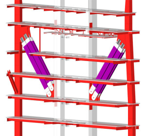
Figure 2. Lower outriggers with “Double-Double” BRBs.
Lower Outrigger BRBs
The Lower (Figure 2) and Upper Outrigger BRBs are connected to the core wall with steel embed plates. Shear studs and half-couplers are welded to the back of the embed plates to satisfy the required force demands. The steel embed plates are up to 4 inches thick and stand over 34 feet tall (Figure 3). Gusset plates are welded to the embed plates to receive the double-pinned connections for the “double-double” BRBs (Figure 4).
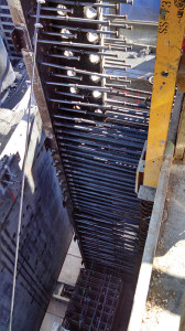
Figure 3. Embed plate for lower.
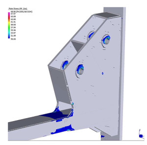
Figure 4. FEA model for connection at core. Courtesy of SIE, Inc.
Due to the height of the embed plates, the Contractor proposed the addition of a “backbone” plate to allow erection of the embed plate as a single unit from the fabrication shop. The “backbone” plates allowed the Contractor to maintain an aggressive construction schedule by eliminating the need to field-weld multiple plates together to provide the required height (Figure 5). The sensitivity of concrete to heat from the welding of the gusset plates led to the use of electroslag welding with tight tolerances of +/- 3/8 inch for horizontal control of the embedment plate.
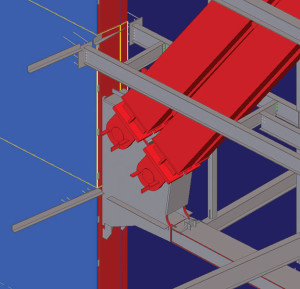
Figure 5. Tekla model for connection at core. Courtesy of Schuff Steel.
SIE, Inc. used a finite element model to analyze and confirm the design of the Lower Outrigger gusset plate connections to the core wall and box columns (Figure 6).
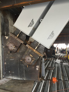
Figure 6. Gusset plates and BRBs installed.
Middle Outrigger BRBs
One of the challenges in designing the Middle Outriggers was the need to accommodate a large “notch” in the outrigger girders adjacent to the core wall for mechanical, electrical and plumbing utilities. Due to the short floor-to-floor height of 11 feet, 6 inches at the hotel levels, the notches are required to provide a path for ducts, conduits and pipes. The outrigger girders at these locations are heavy W33 members connected to an embed plate with a gusset plate and pin. Each girder was reinforced with plates to provide the required strength at the notch. Figure 7 shows the schematic detail of the connection of the W33 girder to the core wall.
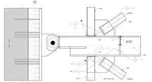
Figure 7. Middle outrigger girder connection to embed plate.
Upper Outrigger BRBs
After completion of the structure, the elastic shortening of the steel will be complete except for that associated with occupant live loads. Due to the thickness of the concrete core walls, it will take approximately 50 years for 75% of the concrete shrinkage to occur. As the core wall shrinks and creeps, the BRBs will go into tension.
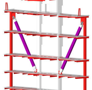
Figure 8. Upper outrigger BRB.
The Upper Outrigger BRBs (Figure 8) are single 2,200-kip braces, which are sensitive to the differential movement between the shrinkage, creep and elastic shortening of the core wall and the elastic shortening of the structural steel box columns. The structural team conducted an extensive study to approximate the anticipated total creep and shrinkage in the core wall. This included a year-long creep and shrinkage testing program of the actual concrete mix used for the core construction, as well as a core construction sequence analysis to evaluate the force transfers based on a construction schedule prepared by the Contractor.
To mitigate the large force transfer due to differential building movements, the BRBs will be jacked with a pre-compression force to 1,000 kips each. This pre-compression in the BRBs will result in a temporary tension force in the exterior box columns. Over time, as the core wall creeps and shrinks, the BRBs will transition from compression to tension, while the exterior box columns will transition from tension to compression.
Conclusion
The structural steel for the building will be substantially complete around March 2016. The scheduled opening date for the hotel and office is the first quarter of 2017. The use of BRBs provided the necessary strength and stiffness in the transverse direction to provide for occupant wind comfort, drift control for wind and seismic, and strain compatibility with creep and shrinkage of the concrete core.▪