
The China Pavilion for Expo Milano 2015
Landmark projects often develop from visions that push boundaries of modern design, forcing designers to think creatively and innovatively. Expanding on the World Expo Milano 2015’s principal theme, Feeding the Planet – Energy for Life, the China Pavilion, designed by Tsinghua University and New York based architecture firm Studio Link-Arc in collaboration with structural engineer Simpson Gumpertz & Heger, centers on ideas of sustainability and the coexistence of nature and cityscape. Its sustainable aspiration presented a challenge and inspiration to architects and engineers alike. Close collaboration and a holistic approach to architecture, engineering, and fabrication enabled the vision of an almost floating wavy timber roof signature structure to be realized (Figure 1).
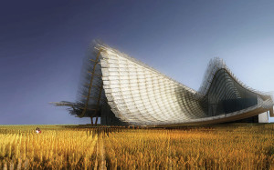
Figure 1. Rendering of the pavilion. Courtesy of Studio Link-Arc.
Engineering Informed Architecture
While sharp-edge angled timber rafter members, resembling a large city skyline, shape the back of the pavilion’s roof, gentle, soft and curvy waves forming the profile of a rolling landscape define the front. Promoting the coexistence of city and nature, these inherently opposing profiles are merged by longitudinal timber members connecting cityscape and landscape to create a ruled surface in between them. An array of parallel rafters forms this gradual transition; sharp angles dominating the roof’s back end are progressively eliminated, allowing the curved portions of the rafters to become predominant towards the front. The rafters, spaced at 6.5 feet (2 meters) on center, and each following a curved line with varying radii, are different in overall shape. The varying curvature of the rafters results in unique shapes for each parallel timber member.
Overall, a rafter-and-purlin solution forming a timber grid system defines the roof’s major concept and geometry. The array of parallel but curved continuous rafters intersects with the longitudinal, mostly straight discontinuous purlin members at regular intervals, creating an evolution of the diagrid, a three-dimensional orthogonal system with moment connections in each primary member axis. This timber structure, utilizing bi-axial moment connections for each orthogonal member connection, is reinforced by substituting exposed steel members of equivalent size and at distinct locations which act as collectors for the long-span diagrid elements.
Several materials and material combinations were considered for the roof structure. The long spans and cantilevers, the complex geometry, the continually varying elevations, and the visual exposure of the structure provided a particular structural challenge; glue-laminated timber (glulam) was selected for strength and stiffness requirements, geometric flexibility, and aesthetics. Glulam members are typically manufactured in standard sizes, but can be custom fabricated into a wide variety of shapes and sizes. The configuration of the laminations allows for complex curved geometries without greatly compromising strength and stiffness. The radius of curvature is limited to roughly 3.3 feet (1 meter). To achieve such a small radius, the laminations must be relatively thin, which can increase cost. If the radius of curvature is roughly 4.4 feet (1.33 meters) or greater, standard 1-inch (25 millimeters) thick laminations can be used and the cost greatly reduced (Figure 2).
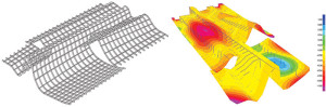
Figure 2. Roof skeleton and deformation contours.
Tradition and Innovation in Detail
Key to the successful execution of significant timber structures is the detailing. Extensive timber engineering knowledge founded on first-hand experience, paired with the team’s drive to innovate and think creatively, led to unique customized detailing that responded to the distinct challenges of the three-dimensional timber grid structure.
The radical geometric form of the structural members plus the very nature of the glulam material (i.e., its orthotropic structural properties and behavior) represent key factors to be understood, considered, and incorporated into the design and detailing. Specific wood-design considerations became paramount through the development of the roof structure including the careful design and detailing of intersections, connections, and bearings, as well as the design of glulam members with extreme curvature.
Extremes in Curvature
The design of curved members requires accounting for two phenomena: the peculiar distribution of the circumferential stresses parallel to the member’s longitudinal axis and the creation of radial stresses perpendicular to the member’s longitudinal axis.
In straight members, plain sections (before the application of a bending moment) are assumed to remain plain sections after bending occurs. Thus, as a result of bending, both longitudinal deformations and material strains (i.e. deformations per unit length) at any given fiber of the section are proportional to the distance of the fiber from the neutral axis. In curved members, however, only longitudinal deformations are proportional to the distance of the fiber from the neutral axis. Strains are not proportional to these distances because the fibers, as viewed across member’s depth, are not equal in length. This leads to larger strains (therefore stresses) at the inside (concave) surface of curved beams; the magnitude of these stresses is directly related to the radius of curvature at any particular point of a beam. As the radius of curvature decreases, stresses increase.
In consideration of this phenomenon, during the iterative design process targeted at identifying the roof’s ideal support points, an overlap and interaction of these inherent stress spikes with potentially coinciding maximum bending moment stresses was avoided.
The creation of radial stresses is another phenomenon of significance that was addressed within the design process. These stresses are a direct result of fundamental engineering-mechanics principles: the free-body diagram of a curved member subjected to a bending moment requires both circumferential and radial stresses for the free-body to remain in equilibrium.
This is a well-known effect covered in several design standards including the American National Design Specification® for Wood Construction (NDS®) and the Eurocode for wood design (EC5), which have been used to estimate radial stresses in extreme curvature regions, such as the peak of the undulated front rafters.
Due to its orthotropic nature, glulam’s characteristic tensile strength for radial stresses perpendicular to the fibers of the laminations is only 72 pounds per square inch (psi) (0.5 megapascals); this is a very small fraction of the material’s strength for stresses parallel to the fibers and is insufficient for locations of extreme curvature of the rafters. The issue was addressed through a series of long, stainless steel, self-tapping screws, designed to be installed along the radial direction, to resist high radial stresses in regions of extreme curvature. The spacing of the screws diminishes as the radius of curvature decreases (Figure 3).
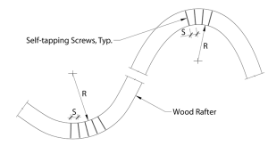
Figure 3. Wood member in extreme curvature.
Detailing Rigidity
Providing sufficient stiffness to the overall roof system in the two orthogonal directions became paramount to limit member sizes and shapes in line with the designers’ vision and led to the design of semi-rigid moment-connections at the rafter purlin interfaces. Considered key parameters are the achievable bending strength and stiffness in the two perpendicular directions (i.e., strong- and weak-axis bending). Following intensive research of literature on the topic, several moment connection types were considered and evaluated in detail, including steel fin plates, serrated surfaces joints, friction welding, embedded and bonded steel plates, through-bolting of cross-laminated wood members, and embedded steel rods with end plates.
Steel fin plates embedded in adjoining wood members and connected to the glulam member by steel bolts provided the most direct load path. However, even when strengthened with an array of self-tapping screws installed perpendicular to the wood grain, these connections did not achieve the required level of moment-resistance and stiffness due to stress concentrations at the bearing surfaces around bolt holes.
Serrated surfaces, when clamped together by steel bolts, eliminate stress concentrations, but experimental results showed this type of connection was not sufficient.
Friction welded wood-to-wood connections work by creating an oscillatory movement between the two surfaces clamped together which, through friction, heats these surfaces to allow a thermo-chemical decomposition of the organic material causing it to be “welded” together. Although very innovative and promising, friction welding could not be selected for this project due to constructability considerations as the purlins needed to be field-connected to the rafters and laser welding in the field is not ideal.
The selected connection detail addressed constructability concerns as well as strength and rigidity demands of the overall roof structure. The purlins are connected to the rafters through embedded, glued, high-strength steel rods connected to steel end plates. A specific resin was specified along with proper embedment lengths and spacing of the rods to establish the desired rigidity for the connection (Figure 4). The proposed connection limits stress-concentration effects, sufficiently strong, provides the desired bi-axial rigidity, and ensures fast assembly in the field. The end plates are connected to the purlins during fabrication in the shop, and include a second steel plate with an offset to allow field placement of the purlins over through-steel rods protruding from the already-erected rafter.
During the pre-construction phase, due to considerations about procurement and lead times and as a result of fabricator specific detailing and fabrication preferences and associated value engineering, the design team decided to relax the established dimensional limits on the depth of the rafters and purlins. The increased member sizes allowed for more flexible purlin-to-rafter connections which became achievable with a simplified embedded steel fin-connection and custom fit steel bolts (Figure 4).
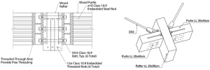
Figure 4. Rafter and purlin connection – initial detail and as built.
Bearing
The geometrical location of the roof structure supports was the result of extensive studies, but was far from being the finish-line of the design. In fact, complex geometry and several constraints in the number and position of the roof supports lead to fairly high reaction forces acting on often-sloped glulam members. A vertical reaction force acting on a sloped section causes longitudinal and perpendicular stresses to the fibers of the laminations. Utilizing the bearing capacity of the wood for the perpendicular component of the reaction, and bolts connected to a steel fin plate (embedded into the member section) to resist the longitudinal component of the reaction, was key to the design of the supports (Figure 5). The introduction of a vertical steel plate embedded through the bottom rafter (the fin plate) interrupts the continuity of the laminations and reduces the capacity of the section. The use of high-strength steel rods brought the section to its original strength. The rods were envisioned to be installed into grooves cut into the laminations during construction of the laminated section in the shop, thus allowing for quality control.
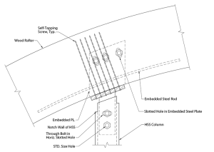
Figure 5. Roof support bearing detail.
The design of these connections also needed to consider (and avoid) the effects of eccentric loading conditions at the reaction points. In fact, the component of the reaction longitudinal to the rafter acts along the centroid of the section, while it is resisted below the rafter, at the interface with the top of a steel column. This configuration creates an arm between reacting forces, and secondary moments may be introduced in the section. A series of slotted holes for the bolts was used to achieve pinned connections to bypass the additional stresses caused by this configuration in the already highly-stressed rafters.
Finally, the volume changes that wood undergoes when subjected to variations in its moisture content was an important consideration. As moisture content increases, wood tends to swell; when moisture content decreases, wood tends to shrink. Steel is not subjected to this phenomenon, and undesirable effects such as cracking may occur if the difference in the behavior of the two materials is not considered in design.
By limiting spacing of the bolts connected to the fin plate, the total change in length of the rafter between two consecutive bolts was accommodated through the play between the bolt-hole and the shank of the bolt. This allowed avoiding additional local stresses in the rafters.
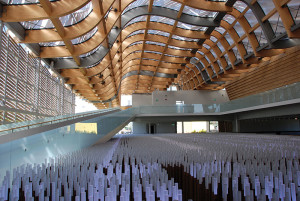
Figure 6. Interior view of long span structure.
Aspirations in Timber
Modern design standards, fabrication techniques, and research allow pushing the envelope of timber design and achieving signature structures like the China Pavilion for the Milano World Expo 2015 (Figures 6 and 7). The devil sometimes literally lies in the details, and great visions cannot materialize without careful review of the interplay of the most fundamental structural components, connections, and members. When profound design aligns with technical advances in engineering and fabrication, new sustainable opportunities can be showcased, an example for what a pavilion hopes to achieve as an educational facility.▪
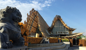
Figure 7. Exterior front view of the pavilion.
Project Team
Structural Engineer: Simpson Gumpertz & Heger
Architect: Tsinghua University + Studio Link-Arc
Architect and Engineer of Record: F&M Ingegneria
Timber Manufacturer: Stratex SpA
General Contractor: China Arts Construction and Decoration Company + Unique Europe + Bodino Engineering
References
1) “Moment resistance of bolted timber connections with perpendicular to grain reinforcements,” Lam F. et al, 10th World Conference on Timber Engineering 2008, v 2, p 978-985, 2008.
2) “Performance of glued-in joints of timber members,” Gattesco N., et al., 9th World Conference on Timber Engineering 2006, WCTE 2006, v 3, p 1848-1855, 2006.
3) “Load displacement and bond strength of glued-in rods in timber influenced by adhesive, wood density, rod slenderness, and diameter,” Aicher S. et al., 1999, 1st TILEM Symposium on Timber Engineering, Stockholm, pp. 369-378.
4) “Moment resistance performance of traditional timber connections comprised of joining and a drift-pin,” Moon-Jae Park et al., 10th World Conference on Timber Engineering 2008, v 3, p 1222-1227, 2008.
5) “Ductile behavior and group effect of glued-in steel rods,” Gehri E., 2001 International RILEM Symposium PRO22 “Joints in Timber Structures,” Stuttgart.
6) “Moment resisting connections composed of friction-welded spruce boards: experimental investigations and numerical strength prediction,” Hahn B. et al., European Journal of Wood and Wood Products, v 72, n 2, p 229-241, March 2014.
7) “Moment-resisting joints using serrated surface,” Idota H. et al., 9th World Conference on Timber Engineering 2006, WCTE 2006, v 3, p 2482-2485.
8) “A review of moment-resistant structural timber connections,” Bainbridge R. J. et al., Proceedings of the Institution of Civil Engineers: Structures and Buildings, v 128, n 4, p 323-331, November 1998.
9) “Performance of joints with eight bolts in laminated Douglas-Fir,” Doyle D. V., United States Forest Products Laboratory Research Paper, FPL-10, Jan. 1964.
10) “Performance of bolted joints in Douglas-Fir,” Doyle D. V. et al., United States Forest Products Laboratory Research Paper, FPL-2, May 1963.
11) “Ductile end connections for glulam beams,” Tommasi R. et al, Structural Engineering International: Journal of the International Association for Bridge and Structural Engineering (IABSE), v 18, n 3, p 290-296, August 2008.
12) “Simplified model for strength assessment of timber beams joined by bonded plates,” Arriaga F. et al, Journal of Materials in Civil Engineering, v 25, n 8, p 980-990, 2013.
13) “The influence of adhesive and bonding techniques on the properties of glued timber-steelplate joints,” Kemmsies M., Swedish National and Testing Research Institute, Building Technology – Wood Section, SP Report 1994:39.
14) “Glulam connection details – Technical Note,” 1999 Engineered Wood Systems.