
The skies above downtown Los Angeles will see a new high rise office/hotel building by March of 2017. Rising out of a 90-foot deep excavation in the earth, the building will dominate the skyline of Los Angeles.
The Wilshire Grand project takes up an entire city block. The site is bounded by Wilshire Boulevard and Francisco to the north, and 7th Street and Figueroa to the south.

The grand pour (Guinness World Record).
Project Description
The project is approximately 2,000,000 square feet with 900 hotel rooms, 400,000 square feet of office space and 45,000 square feet of retail space. The five-level subterranean parking covers the entire site and will accommodate 1,100 vehicles. The structure will have a rooftop pool with ocean views, highly advanced pressurized double decker elevators, an architectural roof top sail and a 200-foot tall architectural spire.
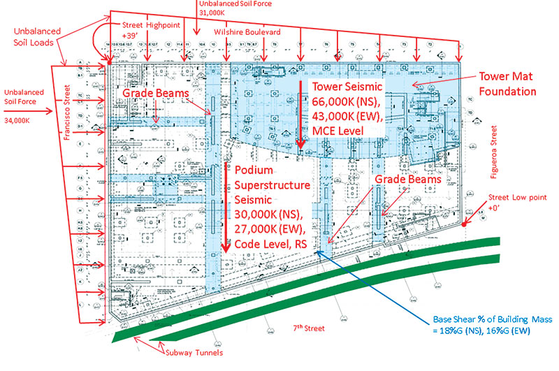
Unbalanced soil loads.
The Tower structure is 73 stories, with the lower floors comprised of office space and the upper 40 floors as hotel rooms. The lateral system for the building is a concrete core wall with concrete filled steel box columns and structural steel framing outside the footprint of the core. The lateral system of the Tower is extremely slender, with a 30-foot wide core wall in the transverse building direction and nearly 1,000 feet tall.
Along the height of the structure there are buckling restrained braced frames to reduce the overturning demands of the core wall on the mat foundation and to stiffen the structure for transverse wind and seismic drift.
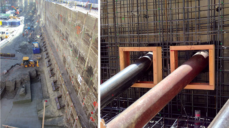
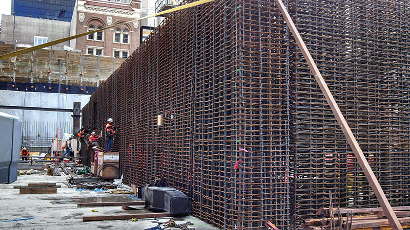
Shoring along 7th street.
In order to meet the aggressive schedule, the project is fast track. The building permits were issued as Foundation Only, Foundation +,
Superstructure part A to the 26th floor, and a “Building Permit Set” to the 73rd floor.
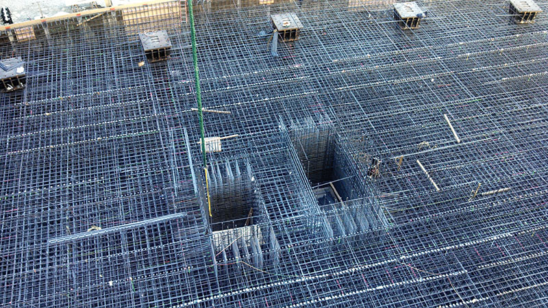
Rat slab with starter columns.
Performance Based Design
The upper 40 floors of the Tower are hotel rooms. To maximize views for all the rooms, it was architecturally important to provide floor to ceiling glass. A conventional code design of this structure would have required a secondary lateral system along with the core wall design. This system would have been some type of steel frame with deep members around the perimeter of the structure where views of the Pacific Ocean were most valued.
The design team selected Performance Based design to eliminate this second lateral “back up” system. A secondary benefit to the Performance Based Design allowed the design team, along with the owner and the peer review panel, to set the performance objectives for the structure.
Len Joseph with Thornton Tomasetti provided invaluable consulting on the performance based design of the Tower and its interaction with the podium structure.
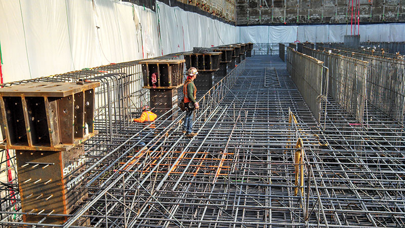
Mat reinforcing with shear reinforcing.
Unbalanced Site Loads
The northwest corner of the site is 39 feet higher than the southwest corner of the site. This unbalanced soil load results in an unbalanced horizontal force of approximately 25,000,000 pounds. This unbalanced force is approximately 80% of the base shear of the Podium superstructure and approximately 50% of the Tower base shear.
In the east west direction, this unbalanced soil force accounts for 23% of the total base shear of the entire project.
The addition of interior basement walls and fin walls off the core walls are required to resist these additional horizontal soil forces. These supplemental basement walls are supported on grade beams as large as 18 feet wide and 12 feet thick, with over 1 million pounds of reinforcing steel.
Elevator pits before top of mat reinforcing.
Shoring
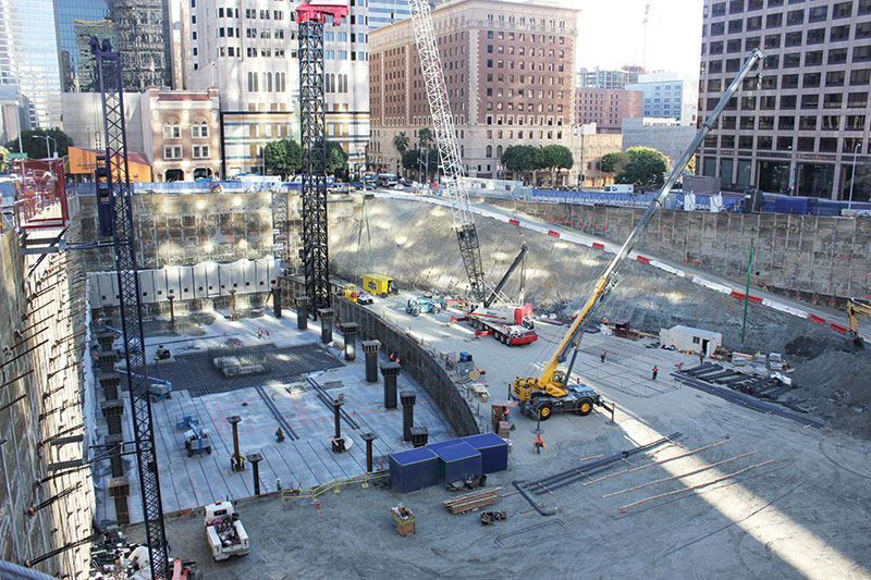
The excavation for the site encompassed an entire city block. There are 316 soldier piles around the perimeter of the excavation. The excavation along 7th Street is as close as 5 feet from the subway tunnel. To provide additional stiffness in the shoring system, rakers were added at 8 feet on center along 7th Street, adjacent to the subway tunnel. The x, y and z coordinates of the tunnel along the length of the excavation are monitored on a daily basis. This will continue until the entire podium structure reaches street level. Because of the removal of the soil adjacent to the tunnel, it has moved vertically approximately ½-inch.
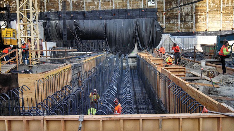
Grade beam with one million pounds of reinforcing.
Lateral Foundation Analysis
The Tower mat foundation was designed for two levels of earthquake resistance, as well as a 1,700 year wind event. The tower was designed for MCE (the Maximum Considered Earthquake – 2% probability of exceedance in 50 years, or 2,475 year return period) site specific response spectra utilizing several damping values, and for the SLDE (Service Level Design Earthquake – 50% probability of exceedance in 30 years, or 43 year return period) site specific response spectra utilizing several damping values. The SLDE earthquake design values were typically 15-20% of the corresponding MCE values.
The Tower was designed for a suite of eleven time histories utilizing a Non-Linear Time History Analysis provided by our consultant, Thornton Tomasetti.
The Podium structure and basement were designed for the prescriptive requirements of the 2010 California Building Code and ASCE 7-05 with a response spectra analysis.
The interaction of the Tower structure with the podium structure and the framed parking levels was worked out by comparison of relative rigidities of each structure between Brandow & Johnson Inc. and Thornton Tomasetti.
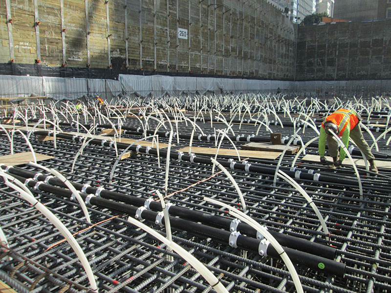
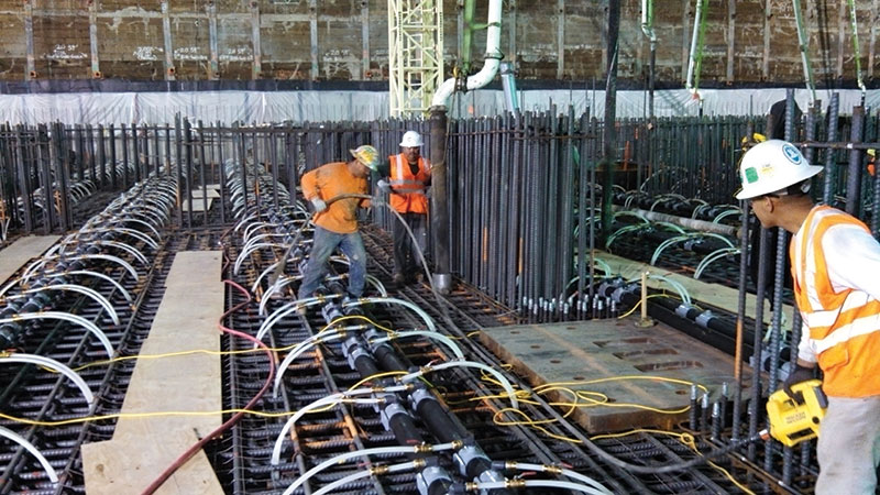
Cooling pipe for mat pour.
Tower Foundation
The foundations for the project are supported on bedrock. The allowable bearing pressures for sustained vertical loads under Allowable Stress Design were 12 ksf and 30 ksf for transient loads at localized areas from wind and seismic forces. The ultimate soil bearing pressure was 90 ksf for localized transient loads under the MCE design event. The footprint of the mat foundation extends past the outside of the Tower to reduce bearing pressures under the mat, and provide more stability for the foundation. Under service loads, the average net bearing pressure under the mat is 12 ksf. Under the maximum considered earthquake (2,475 year return period) the bearing pressures are as high as 58 ksf in small localized areas.
The vertical loads from the core wall and the applied loads on the mat foundation are so great that it is anticipated that the 18-foot thick mat will dish approximately 1 inch under the weight of the core wall, and the mat will settle approximately 2 inches from the weight of the tower.
The foundation for the Tower was poured in mid-February of 2014. It set a Guinness Book world record for the largest continuous concrete pour in history. The USC Marching Band led the first concrete truck. In total, 21,200 cubic yards of concrete were poured in 18.5 hours between Friday night and Saturday morning. The mat pour was 17 feet – 6 inches thick and had 6.7 million pounds of reinforcing steel.
Vibrating the mat pour.
The original reinforcing in the bottom of the mat was 13 layers of #11 @ 6-inch on center each way. The reinforcing steel subcontractor was concerned about placing these bars and threading the headed #9 shear reinforcing through a clear space of 4½ inches. To alleviate this congestion, #18 bars with couplers were utilized. The bottom mat reinforcing was modified to 13 layers of #18 bars at an average of 15-inch on center. Since #18 bars may not be lapped spliced, mechanical couplers were utilized to join the bars. Each of these bars had to be hand spun onto the coupler and tightened with a torque wrench.
In the top of the mat are 4 layers of #11 bars at 12-inch on center. To reduce the amount of reinforcing required, grade 75 ksi steel was utilized throughout the mat foundation. In the center portion of the mat, bars were spaced at 4 feet on center max in each direction for temperature expansion and contraction, and to provide support for the cooling pipe.
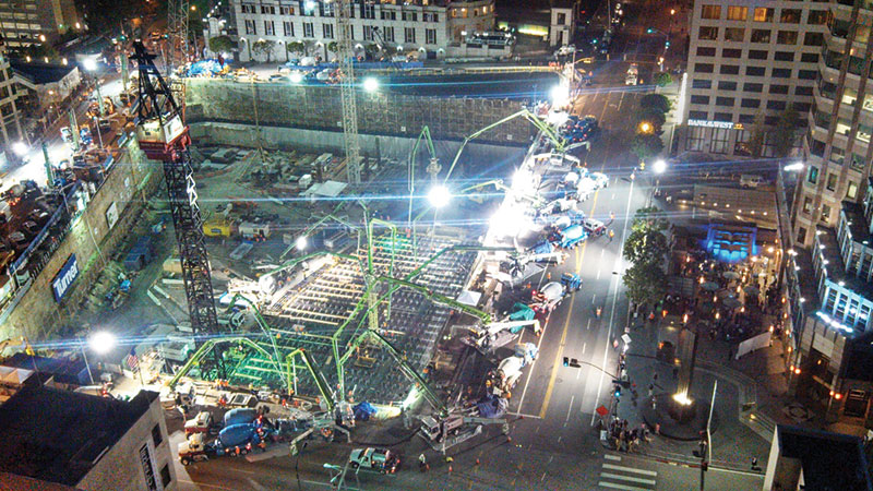
Night time photo of grand pour.
Concrete Temperatures
Mat
The heat of hydration was so great due to one continuous pour, the concrete temperatures were predicted to exceed 160 degrees without mitigation. To combat this, an active cooling system with on-site cooling towers was provided. Approximately 2,000 vertical loops of ¾-inch PEX pipe were manifolded together to remove heat from the concrete. This cooling system was left in place for two weeks for continued heat removal.
Another concern with the temperature of the concrete was the differential temperature from the interior to the exterior of the mat. We were limited to a maximum 35 degree temperature differential from the exterior edge to the core of the mat. In order to keep the extreme edges of the concrete from “catching cold”, thermal insulation was added on the top of the mat to keep the concrete warm. This thermal insulation was left in place for two weeks. The Contractor waited patiently for two weeks to get on the mat to start forming the core wall.

Insulating the mat for two weeks to keep extremities warm.
Core Wall
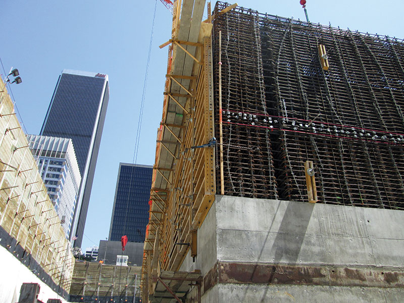
The concrete shear walls at the base of the structure are 48 inches thick and heat of hydration was always a concern for the design team. Initially it was planned to build a mockup of the 48-inch wall, with thermocouples to monitor temperature and reinforcing to model congested areas of the walls. Due to the nature of the schedule, time did not allow for a mockup. To provide the design team with a level of comfort, the Contractor retained a concrete expert from Illinois. Computer models were made to simulate the heat of hydration, and the concrete mix and cement were analyzed. It was determined that the core wall concrete was DEF (Delayed Ettringite Formation) susceptible. DEF is a type of internal sulfate attack on concrete.
First lift of corewall reinforcing.
In order for DEF to be an issue, three things need to be present:
- Unfavorable Cement Chemistry – 12% fly ash in the concrete and unfavorable cement chemistry.
- Long Term exposure to water – concrete core wall exposed to the elements for 1½ to 2 years.
- Temperatures over 160 degrees – with a large amount of cement in the mix, a great deal of heat of hydration, and warm summer temperatures in Los Angeles, this was an issue.
To avoid DEF, it was necessary to chill the concrete mix so that concrete temperatures would never exceed 160 degrees. Los Angeles had numerous days where the ambient air temperature has exceed 100 degrees. Typically concrete can be delivered at point of placement as warm as 90 degrees; to avoid DEF, concrete delivery temperatures were limited to 70-75 degrees.
Typical corewall reinforcing.
The reduced concrete delivery temperature retarded the mix from maturity, which complicates the 4-day cycle of the concrete core wall. The Contractor’s schedule requires that the form system be jumped 12 hours after the pour. With lower delivery temperatures of concrete and slower maturity, the concrete is reaching approximately 1,000 psi at 12 hours. It was initially assumed that the concrete would reach 2,500 PSI at 12 hours. This created schedule problems with the coil inserts utilized in the core wall to jump the form system. Currently, test protocols are under development to demonstrate a safety factor of 3 in the design loads of the form system for 1,000 psi concrete.
Conclusion
The Wilshire Grand Hotel/Office building will continue rising from the ground over the next three years. In late 2015 the structure should top out, with the remaining time devoted to the completion of the architecture and building skin.
This will be the tallest structure west of the Mississippi. Outside of New York and Chicago, it will be the tallest structure in the United States. It will be the only highrise building in Los Angeles without a flat roof top, redefining the Los Angeles skyline with its elegant sail atop the structure.▪