
By Brian MacRae, P.E., S.E., Kerem Gulec, Ph.D., P.E., S.E.
The ambitious goal of transforming the existing Key Arena in Seattle, Washington, into a world-class sports and concert venue was undertaken by its owners at Oak View Group, who challenged the project team to develop numerous innovative and collaborative solutions. Opened in October 2021, Climate Pledge Arena is home to the NHL’s newest franchise Seattle Kraken and WNBA’s Seattle Storm. The total transformation of the venue serves as a structural engineering benchmark for existing building renovations in high seismic zones and demonstrates what can be accomplished with modern design and analysis techniques.
Following the classification of the existing roof and curtain wall as local landmarks by the Seattle Landmarks Preservation Board in 2017, the structural engineering team at Thornton Tomasetti was tasked with solving how to seismically retrofit the existing structure while not impacting the original early 1960s aesthetics, designed by modernist architect Paul Thiry. That challenge was complicated by the fact that the entire primary lateral force resisting system of the roof is composed of exposed concrete elements. The design team’s solution included developing a project-specific basis of design document and acceptance criteria and implementing a comprehensive state-of-the-art nonlinear dynamic analysis procedure. These procedures allowed the team to incorporate realistic analysis boundary conditions at the foundations, soil-structure interaction effects, and seismic fuses to control the demands on the existing structure.
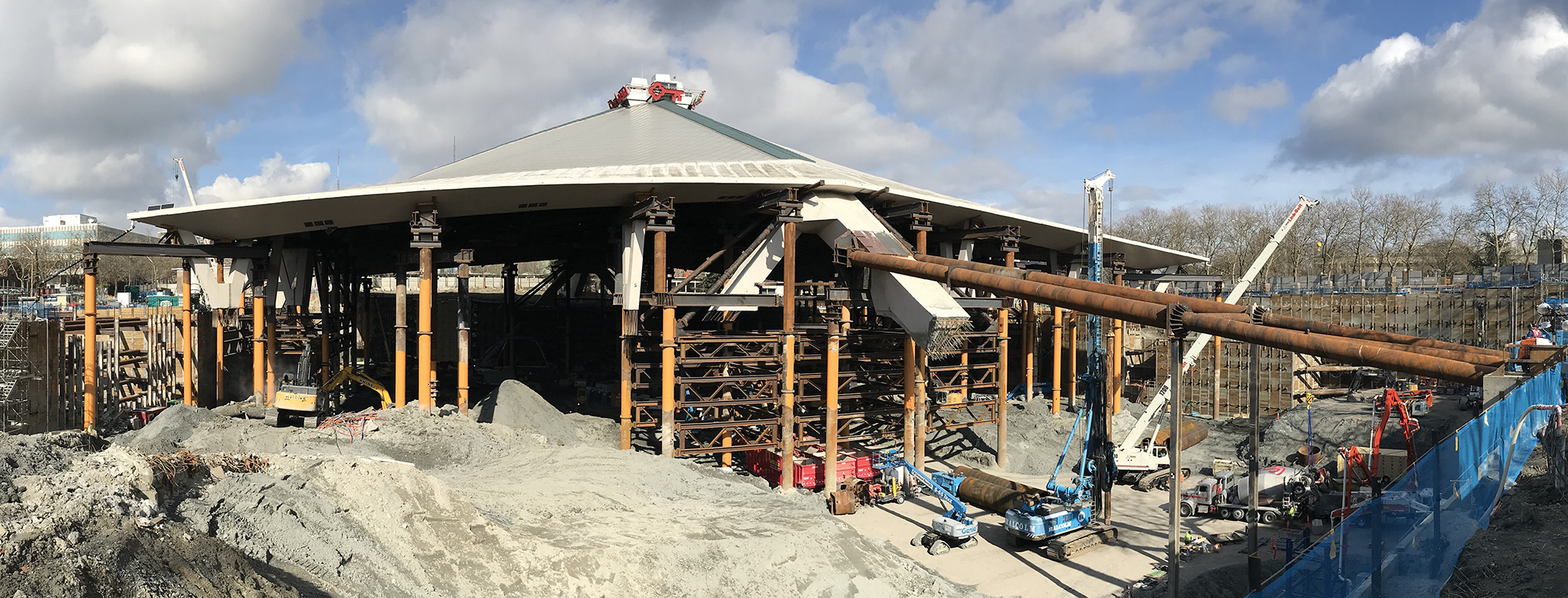
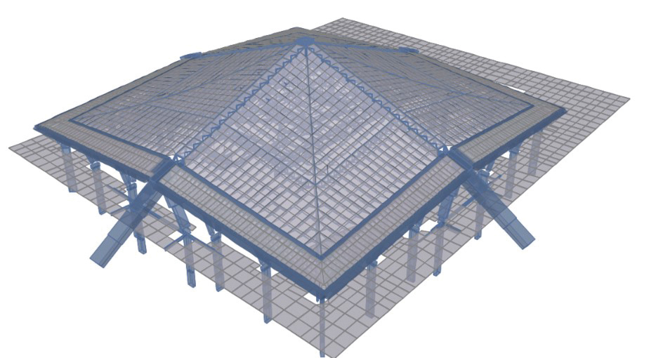
Given the confines of the historic curtain wall, aside from the new south glass atrium, which will welcome incoming sports and music fans for years to come, the only option to expand the arena to meet the needs of a modern venue was to extend the footprint an additional 15 feet below its current event level floor to construct four new steel framed levels and a parking garage at and below the existing grade. These new floors extend laterally beyond the original roof foundations and resist seismic loads through new concrete basement walls, shear walls, and buckling restrained braced frames. The interface of the existing concrete roof supports and the new below-grade floors occurs at the surrounding grade elevation at the upper concourse level. Over 680,000 cubic yards of soil was excavated and foundations for 20 Y-columns, eight chevron legs, and the south concrete buttress were demolished to allow for the below-grade expansion. New concrete walls and columns were installed to carry the gravity and seismic loads from the existing concrete elements another 55 feet down to new pile foundations. To support the excavation, 178,000 square feet of permanent shoring was installed composed of 500 soldier piles and 130,000 linear feet of tiebacks. The roof was underpinned on 67 temporary drilled shafts with over 3,700 tons of temporary steel installed spanning to the drilled shafts to resist seismic and gravity loads during construction (Figure 1).
The Roof Structure and Its Load Path
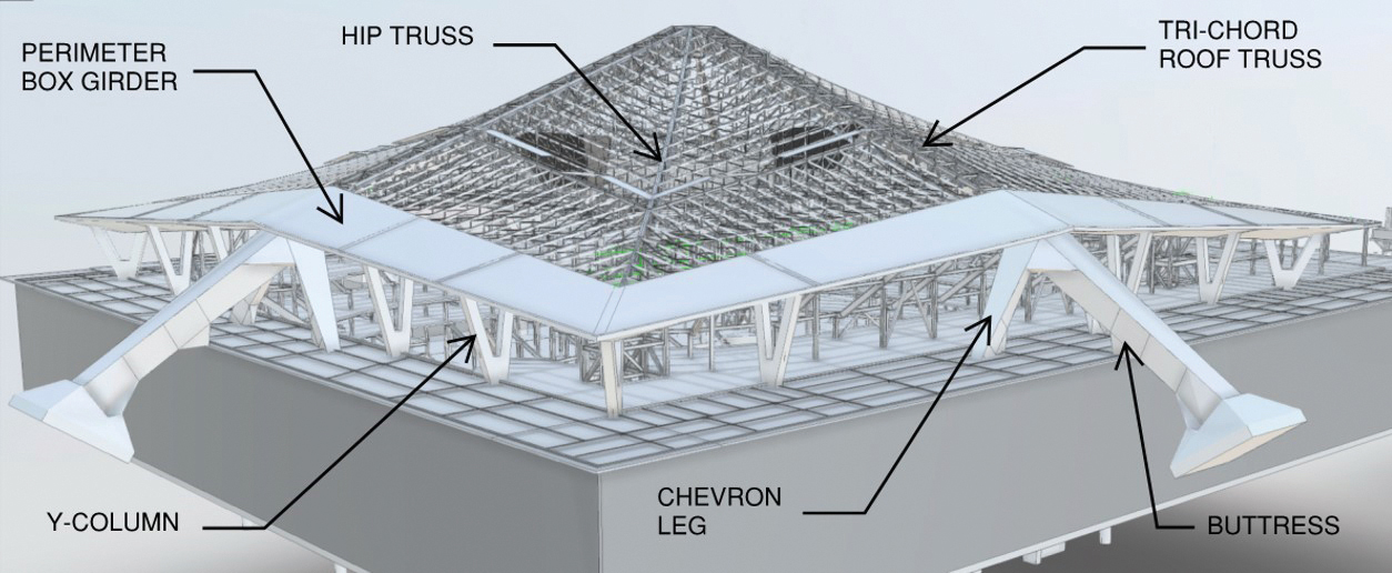
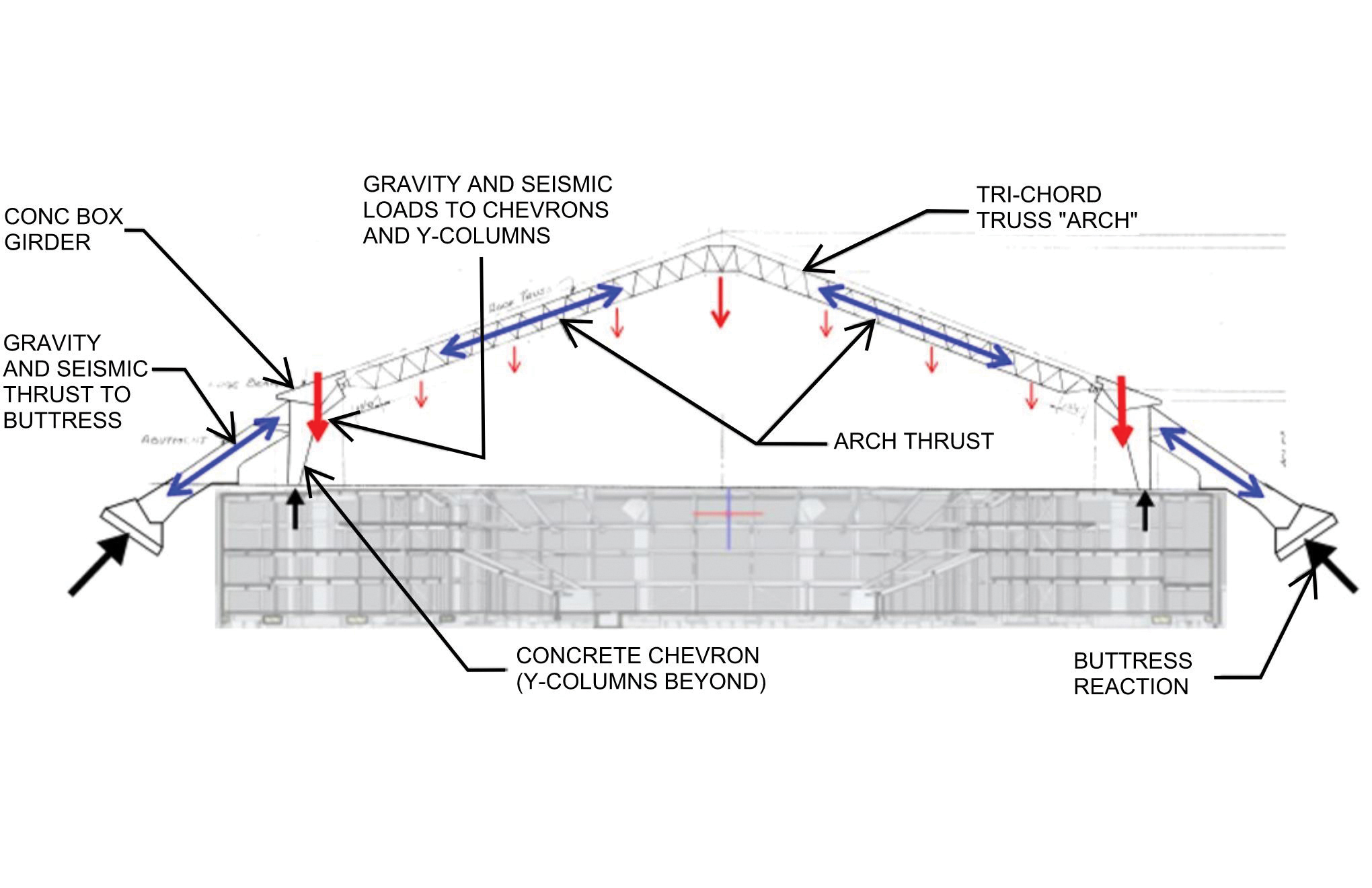
The structural system of the existing 400-foot-x-400-foot, 44-million pound roof comprises four primary tri-chord steel arch trusses, which deliver gravity and seismic loads to four tapered trapezoidal concrete buttresses. Buttresses have maximum out-to-out dimensions of 12 feet x 12 feet and extend diagonally outward at the midpoint of the four sides of the square roof down to concrete spread foundations. An approximately 30-foot-wide by 14-foot-deep multi-cell post-tensioned concrete box girder is located at the perimeter of the roof. Spanning between the box girder and the tri-chord trusses are 272 infill trusses supporting a 1-1/2-inch bare metal roof deck. The perimeter box girder is supported by 20 Y-shaped columns at 20-foot on-center spacing and four pairs of large tapered trapezoidal concrete chevron braces oriented perpendicular to, and centered on, the four concrete buttresses. While the Y-columns resist a small percentage of the lateral forces, the buttresses and chevron braces resist most of the lateral loads. Further details of the structural system and gravity and lateral load paths can be seen in Figures 2 and 3.
Verifying Existing Conditions
The evaluation of any existing structure starts with an understanding of the construction materials and condition of the structure. Fortunately, original construction and renovation drawings, which included structural framing modifications, were available for the roof. This was crucial, as a much more substantial testing and investigation program would have been required to document the structural framing geometry, materials, and reinforcing details. Except for some connections from the minor trusses to the perimeter box girder, the general condition of the landmark structure was good.
Existing building drawings were used to develop a SAP2000 analysis model of the building. Additionally, laser scanning was done to verify the existing conditions against the information obtained through the drawings.
Seismic Evaluation Approach
Seismic evaluation of existing buildings requires developing a project-specific evaluation and acceptance criteria using available standards such as ASCE 41 or available information in the literature (e.g., experimental data). A project-specific Basis of Design Report and a performance-based seismic evaluation approach utilizing applicable parts of ASCE 41-13 was used for the retrofit.
The arena is in a high seismic zone with nearby major faults that have the potential to generate large and destructive earthquakes. The closest to the site is the Seattle Fault, about 3 miles south. One significant design challenge was that the original roof was designed to significantly lower lateral force demands than the current-day building codes require. The design objective was to evaluate the seismic performance of the existing roof with current seismic hazards and retrofit as required to bring it to acceptable seismic safety and performance. In addition to the retrofits required for seismic deficiency, new loading was introduced onto the roof (e.g., rigging, scoreboards) as part of the renovation. Structural performance was evaluated at both the Damage Control level for BSE-1E (225-year return period) and Limited Safety for BSE-2E (975-year return period) hazard levels, satisfying the basic performance objective for an existing Risk Category III structure (BPOE).
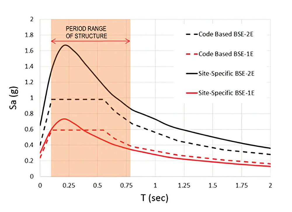
A Probabilistic Seismic Hazard Analysis (PSHA) performed as part of the site-specific ground motion hazard study conducted by the geotechnical engineer, Hart Crowser, identified several other sources (local and distant faults) that contribute significantly to the overall seismic hazard at the site. The site-specific spectra accounted for local soil and geological conditions, including the Seattle Basin effects, which resulted in spectral accelerations of 25% to 50% higher than the ASCE 41 code-based spectra. For comparison, Figure 4 shows the two hazard spectra (code vs site-specific) for the same hazard levels.
Subsequently, these spectra were modified to account for kinematic soil-structure interaction effects, which typically result in reduction of spectral acceleration demands at the short periods and do not impact acceleration demands on longer periods. At the period of the structure, this reduction was about 20%; therefore, some of the increases due to basin effects were offset by the application of kinematic soil-structure interaction effects.
Four analytical procedures are outlined in ASCE 41: linear static, linear dynamic, nonlinear static (pushover), and the nonlinear dynamic methods (listed in increasing analytical complexity). For the seismic evaluation of the roof, nonlinear dynamic analysis method was used, which is the most complex of the four methods, requiring by far the most analytical work. Use of complex performance-based seismic design procedures such as this one also requires an independent peer review in addition to the review of the Authority Having Jurisdiction (AHJ). This peer review team may include members from academia and industry practitioners with expertise in ASCE 41 procedures, including advanced analysis topics such as nonlinear dynamic analysis.
Despite its complexity, this method was chosen due to the following reasons:
- The structure contains an unusual lateral force resisting system which is not listed as one of the Common Building Types described by ASCE 41. Nonlinear modeling of certain structural elements/actions were crucial, and in this case linear analysis methods would not be able to capture seismic behavior reasonably. A nonlinear behavior will allow realistic modeling of boundary conditions for the buttresses and fuses in the new substructure that will be used to limit the tension forces in the chevron braces.
- Nonlinear dynamic procedure (or nonlinear response history analysis) is the most accurate analysis in predicting seismic behavior. Considering the significance of the structure, it was thought to be the most appropriate analysis method.
In essence, nonlinear dynamic procedure requires creating a nonlinear analysis model of the building and subjecting that analytical model to ground motions developed by the geotechnical engineer, specifically for that site and building. At that time, seven ground motion records were allowed by ASCE 41-13 and were used (current practice is using 11 ground motion sets). These acceleration records included two horizontal components of the shaking and the vertical component.
For most buildings, vertical acceleration records are not explicitly used in design. However due to the unique framing (long span, sloping trusses, etc.), it was decided early that vertical accelerations would need to be explicitly captured in the analysis. This also requires a more refined analytical model, as a sufficient number of vertical vibration modes, typically not critical for the seismic design of most buildings, need to be captured.
Analytical Modeling & Soil-Structure Interaction
A 3D mathematical model was created in SAP2000 to analyze the roof that included all the primary structural components of the existing structure, the new rigging grid, and the new upper concourse diaphragm, as shown in Figure 5. A separate linear dynamic analytical model was developed in SAP200 for analyzing the new below-grade portions of the arena. Transfer loads from the existing roof model were superimposed onto the base-structure model to study the full load path through the new below-grade lateral system. The existing roof analytical model was quite heavy, with 600 nonlinear links, and 10,000+ frame and 6,000+ shell elements. The roof truss elements and columns were modeled as line elements. The roof deck and box girders were modeled using thin shells. The model also had to include a newly introduced rigging frame, which was laterally stabilized to the roof using buckling restrained braces.
Nonlinear actions like the fuses introduced in the new substructure under the base of the chevrons and interaction of the buttresses with soil were modeled explicitly. Further details of the chevron fuses can be found in the design and construction section below. The north, east, and west buttress spread footings were modeled using nonlinear force-deformation curves with both translational and rotational stiffness (Figure 6). The interaction of the structure, foundation, and supporting soil-structure interaction (SSI) is an important feature of the mathematical model which can impact the demands imposed on the structure for a simulated earthquake. The sensitivity of the structural response was tested by varying the foundation stiffness parameters from the calculated values determined in accordance with ASCE 41.
Analysis Workflow
Considering the size and complexity of the project, design and construction schedules were very aggressive. As previously explained, nonlinear response history analysis was deemed appropriate for the seismic analysis, a procedure that required significantly more analysis and pre- and post-processing time than conventional linear procedures.
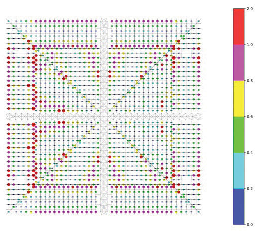
It was clear from the beginning that the analysis and post-processing workflows had to be very efficient and flexible. A significant number of analysis iterations was expected to quickly study new additions/modifications and evaluate effectiveness of the considered retrofits. At each iteration, a full set of ground motions was run, and results were quickly developed and screened to verify if intended changes were viable. Project-specific post-processing scripts were written in the Python programming language to enable quick and efficient visualization of results. An example of these outputs is shown in Figure 7.
Design & Construction
In hockey, a team can have a meticulous game plan, simulated through reps on the practice ice. However, success is ultimately gauged by how the team executes this plan when the fans fill the seats and the puck drops. Similarly with a structural team, a sophisticated and accurate analysis approach and model provide little value to the finished project if they do not translate into a cost-efficient and constructable solution executed by qualified tradespeople. The successful seismic retrofit of Climate Pledge Arena would not have been possible without the collaborative execution of the team led by owner OVG, owners representative CAA Icon, architect Populous, structural engineer Thornton Tomasetti, and construction manager Mortenson.
The most challenging conditions to resolve were at the interface of the roof’s concrete elements with the new steel bowl and garage structure, at and below grade. To preserve the roof’s aesthetics and limit the number of retrofits required within the existing roof trusses, the design team strived to limit changes in the roof’s lateral load path to the full extent possible.
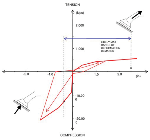
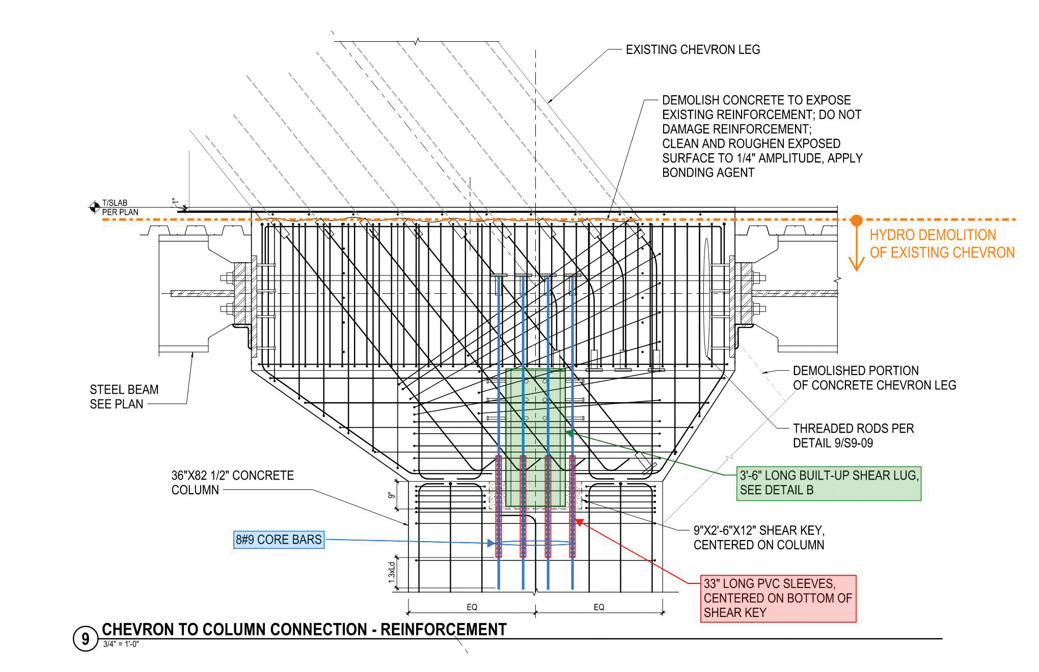
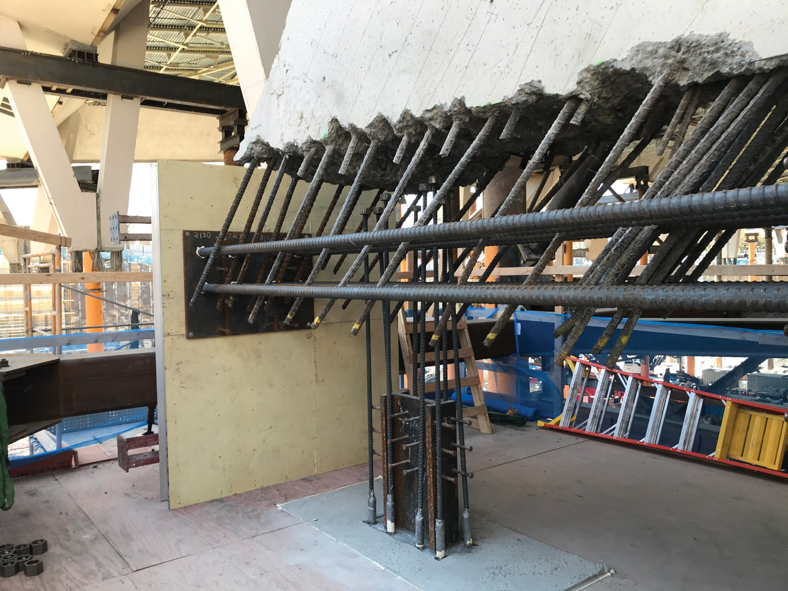
One such interface condition is where the four pairs of chevron braces meet the new upper concourse steel composite floor framing at the existing grade level. At this interface, a concrete node measuring 13 feet x 6 feet 8 inches was designed to fully capture the angled chevron leg from above and transfer loads to the horizontal collector beams in the upper concourse diaphragm and the new 7-foot x 3-foot concrete column below. This new column would transfer the vertical reaction to a new pile foundation 55 feet below grade. The existing chevron legs had limited tension capacity which the design team resolved by designing a fuse in the new node to limit the tension forces that could be delivered through the chevron leg. This was accomplished by installing eight #9 bars vertically in unfilled 33-inches long PVC sleeves to allow both ductile yielding and the force to be capped by the post-yield capacity of the bars. To finish out the detailing of the node an embedded steel shear lug was designed to transfer shear loads across the fuse interface. Additionally, eight #18 Grade 80 Dywidag threaded rods were installed horizontally through the node to transfer seismic forces to the steel collectors in the upper concourse. The existing reinforcing in the chevron brace was preserved using hydrodemolition techniques to be developed into the new node. Hydrodemolition consists of blasting the existing concrete with high-pressure water exceeding 20,000 psi using a robot. It has the effect of removing all concrete and exposing the existing reinforcing undamaged to allow for embedment into new freshly poured concrete.
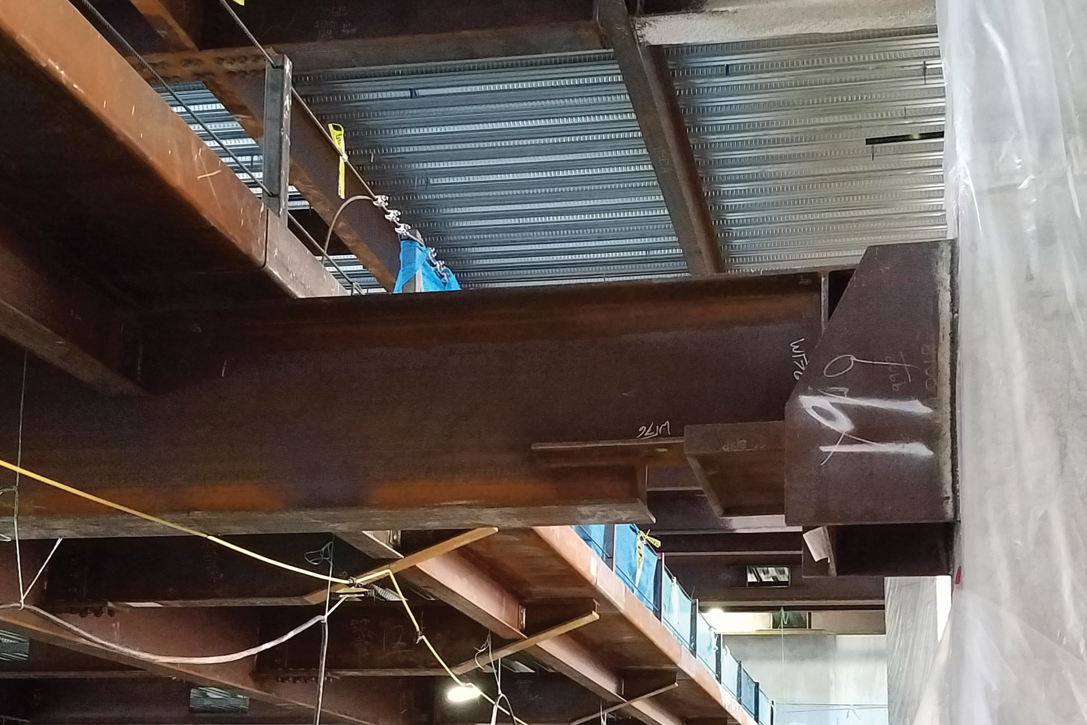
As the design efforts progressed, the structural team discovered that the new boundary conditions for the roof were introducing excessive shear and torsion forces in the Y-columns due to their unique geometry and connection to the bowl framing below. These existing columns were minimally reinforced for shear. While introducing a fiber wrap solution to resolve the issues in the Y-columns was considered, it was deemed infeasible due to the aesthetic requirements. As such, the design team developed a solution to laterally release the Y-columns from the upper two levels of the new below-grade framing using low-friction slider connections at each steel beam to Y-column connection. This solution had the effect of lengthening the Y-column’s unbraced length, and in turn, reducing its stiffness and ability to attract seismic loads. This creative solution resulted in all 20 Y-columns being able to withstand the seismic forces induced by the roof displacements and eliminated all retrofits of the existing Y-columns.
After the design challenges at the roof/bowl interface were resolved, the design team focused on the seismic retrofits required within the existing roof steel. The new rigging grid, capable of supporting shows of up to 200,000 pounds, was seismically braced to the existing roof trusses using Buckling Restrained Braces (BRB). This reduced the number of required steel retrofits by limiting the forces that could be delivered from the grid to the existing steel roof. Retrofits throughout the roof were primarily truss web and chord strengthening through additional welded and bolted steel plates, channels, and angles.
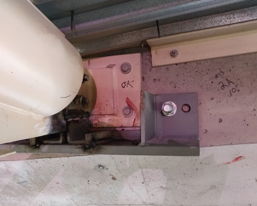
One connection of concern in the existing roof was at the infill truss to perimeter box girder connection (Figure 11). It consisted of a steel plate flush with the face of the box girder with four expansion bolts. This connection was found to be susceptible to premature failure under axial load in a large seismic event. To remedy this, a catch shelf was designed below the connection to support the truss in case of anchor failure, and a nonlinear link was introduced in the analysis model to represent the condition. Without nonlinear analysis techniques, accurately modeling the behavior of the final solution would not have been possible.
Conclusion
Climate Pledge Arena is an award-winning retrofit and rehabilitation project unlike any other. The complexities and challenges involved with temporarily supporting a 44-million-pound roof in the air while building a completely new arena below was a monumental feat of engineering, design, and construction. Utilizing modern techniques in nonlinear analysis and performance-based design, the structural design team was able to develop creative and innovative engineering solutions without limitations. While such an analysis procedure may not suit every project due to the potential impact on schedule and design fees, it can be an incredibly valuable tool for an experienced structural engineer dealing with complex and unique building structures. ■
Brian MacRae, P.E., S.E. is an Associate Principal with Thornton Tomasetti in Seattle, WA. He can be reached at bmacrae@ThorntonTomasetti.com.
Kerem Gulec, Ph.D., P.E., S.E. is a Principal with Thornton Tomasetti in Los Angeles, CA. He can be reached at cgulec@ThorntonTomasetti.com.