
As a Distinct Seismic Force-Resisting System in ASCE/SEI 7-22
Coupled composite plate shear walls/concrete-filled (coupled C-PSW/CFs), known as the SpeedCore system by the American Institute of Steel Construction (AISC), is a non-proprietary composite solution for the design of mid- to high-rise buildings. The coupled C-PSW/CF system is a revolutionary modular system that reduces the construction schedule considerably. The coupled C-PSW/CF system provides adequate lateral stiffness, capacity, and ductility (deformation capacity) needed to be considered as a primary seismic force-resisting system. This structural system is an alternative to conventional coupled reinforced concrete walls in the wind or seismic design of buildings. A typical coupled C-PSW/CF system using planar C-PSW/CFs and composite coupling beams (CBs) is shown in Figure 1.
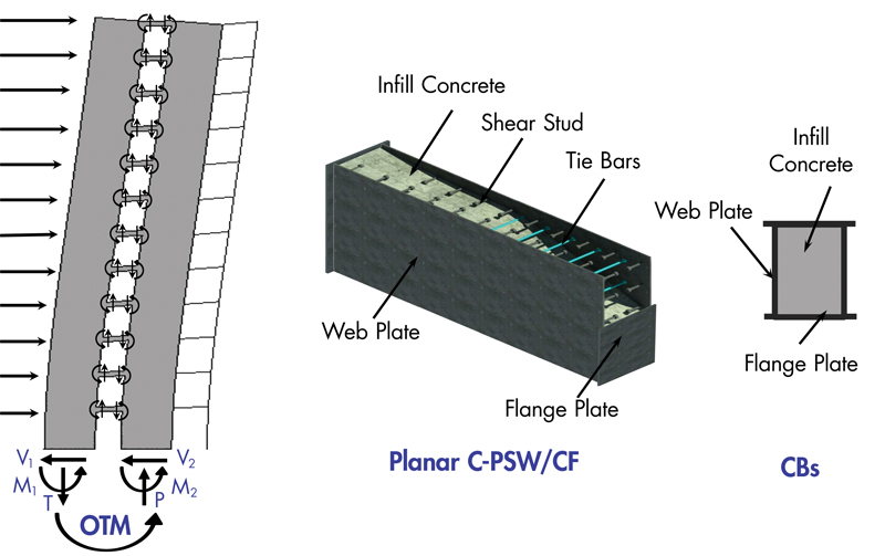
The planar C-PSW/CF consists of steel plates and infill concrete (plain concrete). Steel web plates are connected to each other using tie bars or steel shapes, and there are flange plates (closure plates) at the ends of the wall, as shown in Figure 1. The steel plates serve as the primary reinforcement of walls; therefore, there are no conventional steel rebars in the SpeedCore system. Instead, a composite interaction between infill concrete and steel plates is developed using tie bars and shear studs. Composite coupling beams are recommended for the seismic design of coupled C-PSW/CF systems.
As evident from its name, the SpeedCore system reduces construction time considerably due to its ability to be installed quickly. Empty steel modules of the coupled C-PSW/CF system – including steel plates, tie bars, and shear studs – are prefabricated in a shop and transported to the site for erection. The erected empty steel modules serve as formwork and falsework during construction and concrete casting. The erected empty modules of coupled C-PSW/CFs can resist a construction load of up to four floors of decking, making it possible to erect the steel modules of the coupled C-PSW/CF system and steel gravity frames simultaneously. The modules can be filled with either normal or self-consolidating concrete (SCC).
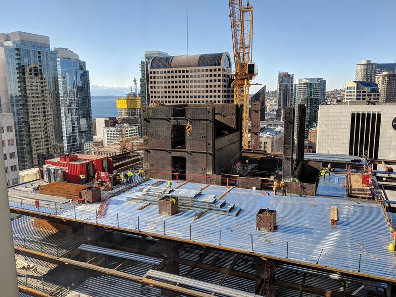
The first high-rise building in the United States to use the SpeedCore system is Rainier Square Tower, constructed in Seattle and designed by Magnusson Klemencic Associates (MKA). This 58-story high-rise building was designed and detailed in a seismic region, although it was a wind-controlled structure. The construction of Rainier Square Tower was completed in 2020, demonstrating the feasibility of applying this novel modular structural system in high-rise buildings. Figure 2 illustrates the erection of Rainier Square Tower’s empty steel modules and gravity frames. The use of the SpeedCore system in Rainier Square Tower resulted in a savings of eight months compared to traditional reinforced concrete core walls.
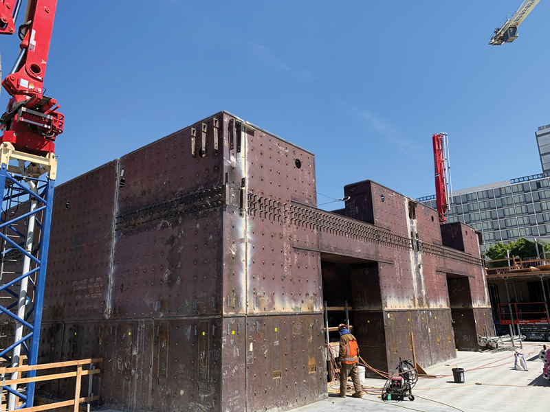
A second project utilizing the SpeedCore system is the 200 Park Avenue high-rise in San Jose, California, under construction at the time of this writing. Figure 3 illustrates a prefabricated empty steel module of coupled C-PSW/CF during the 200 Park Avenue tower construction. Implementing the coupled C-PSW/CF system in this 19-story office tower shaved three months off the construction schedule. Employment of the SpeedCore systems in the mentioned projects resulted in faster construction with remarkably reduced costs compared to traditional reinforced concrete core walls.
Seismic Design Philosophy
Coupled C-PSW/CF systems in mid- to high-rise buildings are designed to resist lateral seismic forces. In the coupled C-PSW/CF system, two or more individual C-PSW/CFs are connected by ductile steel or composite coupling beams. To make a coupled C-PSW/CF system, the individual C-PSW/CFs can be planar, C-, U-, I-, or T-shaped composite walls. As a result, the coupled C-PSW/CF system has a totally different lateral seismic response than uncoupled individual C-PSW/CFs.
In the seismic design of a coupled SpeedCore system, coupling beams and C-PSW/CFs are sized using a capacity design principle. The coupled C-PSW/CF system is expected to undergo significant plastic deformation at the ends of coupling beams along the structure’s height, followed by the yielding of C-PSW/CFs at the base during a large earthquake event. It is recommended in AISC 341-22, Seismic Provisions for Structural Steel Buildings (Section H8), that composite coupling beams be sized to be flexure-critical members. Implementing strong C-PSW/CFs and weak coupling beams is the seismic design philosophy of the coupled C-PSW/CF system.
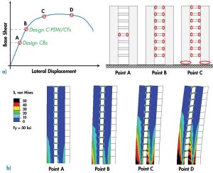
Figure 4 shows the seismic design philosophy of the coupled C-PSW/CF system and a lateral load response (nonlinear static pushover analysis) of a 12-story coupled C-PSW/CF structure using finite element modeling. The composite coupling beams are designed for code-level seismic forces and have flexural yielding at both ends (Point A). The individual C-PSW/CFs are sized to have flexural yielding at the base after formations of plastic hinges in all coupling beams along the height of the structure (Point B). In other words, the C-PSW/CFs are sized for an amplified base shear, as shown in Figure 4a, which is calculated according to the capacity limit forces from the composite coupling beams and the coupling action.
While the flexural plastic hinges are forming at the base of C-PSW/CFs due to the increase in lateral displacement, the lateral load capacity of the coupled C-PSW/CF system increases until fracture initiations in the composite coupling beams take place (Point C). This milestone is considered the ultimate lateral capacity for the coupled system. The ratio of the ultimate capacity to flexural yielding of coupling beams (Point C to Point A) is defined as the overstrength factor.
Finally, the lateral load capacity of the coupled C-PSW/CF system starts to decrease due to fracture initiations in C-PSW/CFs at the base (Point D). As shown in Figure 4b, the finite element model of a 12-story coupled C-PSW/CF structure verifies that the lateral load behavior follows the aforementioned seismic design philosophy.
Dynamic Response
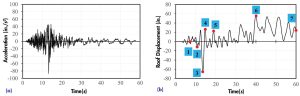
The lateral seismic response of the 12-story coupled C-PSW/CF structure discussed above was evaluated using nonlinear dynamic time-history analysis. Seven different far-field ground motions were chosen for the nonlinear dynamic time-history analyses. The ground motions were scaled to the design basis earthquake (DBE), maximum considered earthquake (MCE), and failure level earthquake (FLE) to evaluate the seismic responses. Figure 5 illustrates the nonlinear time-history response of the structure subjected to Superstition Hills ground motion (El Centro Imp. Co. 1987) scaled to a spectral acceleration of 1.83g (FLE).
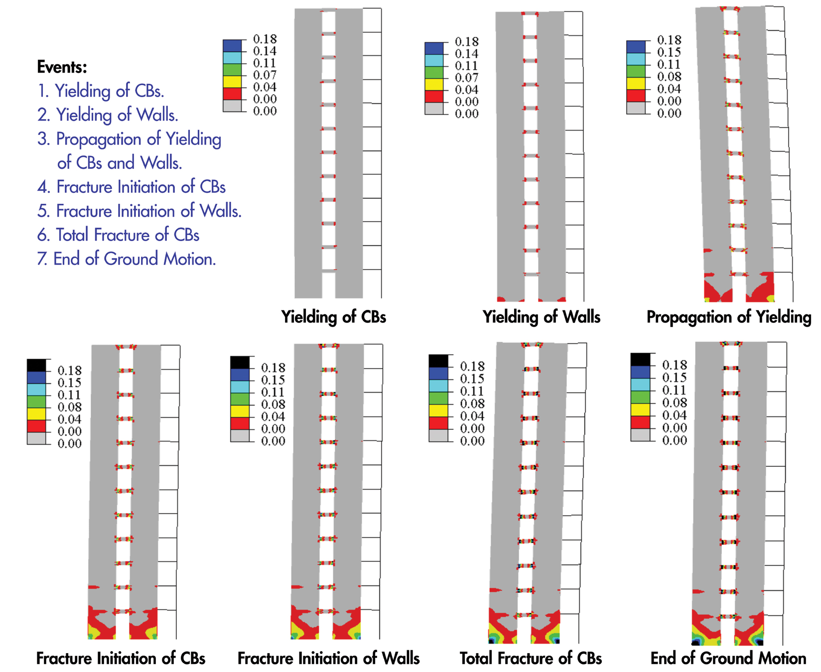
For the DBE and MCE levels, the maximum inter-story drifts of the 12-story coupled C-PSW/CF structure were 0.95% and 1.43%, respectively. The coupled C-PSW/CF structure experienced flexural yielding in coupling beam ends (without any fractures), followed by some yielding at the base of each C-PSW/CFs at the DBE. Similarly, the coupled C-PSW/CF structure underwent flexural yielding in coupling beams (without any fractures), followed by yielding at the base of C-PSW/CFs at the MCE. The propagation of yielding was noticeably greater at the MCE level than at the DBE level. The ground motion was scaled to a spectral acceleration of 1.83g (FLE) to investigate the failure mode of the structure. The coupled C-PSW/CF structure underwent the following milestones: 1) flexural yielding of coupling beams, 2) flexural yielding of C-PSW/CFs, 3) propagation of yielding, 4) fracture initiation of coupling beams, 5) fracture initiation of C-PSW/CFs, 6) total fracture of coupling beams. Figure 6 illustrates the occurrence of major events, which is in accordance with the aforementioned design philosophy.
Seismic Design Factors
All prescriptive seismic design codes for different structural systems use three seismic factors: (i) a response modification factor, R, (ii) an overstrength factor, Ωo, and (iii) a displacement amplification factor, Cd. These three seismic factors are defined for each structural system based on the system-level inelastic response, ductility, failure mechanism, and other seismic factors.
The response modification factor, R, is specified for each structural system based on the inelastic response and system-level ductility. The R factor is used to reduce the base shear for the linear elastic design. The overstrength factor, Ωo, is specified as the ratio of the ultimate capacity of the structural system to the first significant yielding. The overstrength factor is used to estimate the ultimate capacity of a structure, considering the failure mechanism, structural redundancy, and material overstrength. The displacement amplification factor, Cd, is the ratio of ultimate inelastic displacement during the MCE to the elastic response of a structure subjected to the code-level seismic forces. The Cd factor is used to estimate the maximum inelastic lateral displacement and drift from the elastic response of the structure.
A study using FEMA P-695, Quantification of Building Seismic Performance Factors, was conducted to evaluate and verify the seismic design factors (R, Ωo, and Cd) for the coupled C-PSW/CF system. The study was collaboratively accomplished by research teams from the University at Buffalo and Purdue University. The results of the FEMA P-695 study show that seismic factors for the coupled C-PSW/CF system are as follows: a response modification factor of 8 (R = 8), an overstrength factor of 2.5 (Ωo = 2.5), and a displacement amplification factor of 5.5, (Cd = 5.5). It should be noted that the response modification factor of 8 is the highest factor that can be assigned for a structural system according to ASCE/SEI 7, Minimum Design Loads and Associated Criteria for Buildings and Other Structures.
Composite Coupling Beam-to-C-PSW/CF Connection
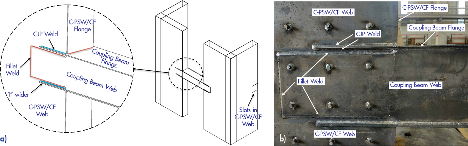
In the seismic design of coupled C-PSW/CF systems, composite coupling beam-to-wall connections are designed and detailed to develop a minimum chord rotation capacity of 0.03 radians before the flexural capacity of the connection decreases to 80% of the plastic moment capacity of the coupling beam. Researchers at Purdue University developed several possible coupling beam-to-C-PSW/CF connections with the help of an industry advisory panel and fabricator inputs. The seismic responses of these connections were experimentally and numerically evaluated. A possible composite coupling beam-to-C-PSW/CF connection is shown in Figure 7. There are slots in the C-PSW/CF web plates, and coupling beam flange plates are inserted into the slots. Coupling beam flange plates are 1 inch wider than the wall cross-section from each side to provide adequate clearance for complete joint penetration (CJP) welding. The slots of C-PSW/CF web plates are beveled and welded to the coupling beam flange plates using CJP welding. The coupling beam web plates are overlapped at the C-PSW/CF web plates, and C-shaped fillet welding is done. The depth of coupling beam web plates is reduced 1 inch from top and bottom at the connection region to provide adequate clearance for fillet welding.
2020 NEHRP Design Example
A seismic design example for an 18-story office building using a coupled C-PSW/CF system is presented in Chapter 5 of the 2020 NEHRP Recommended Seismic Provisions: Design Examples, Training Materials, and Design Flow Charts (FEMA P-2192-V1). The design example shows the step-by-step seismic design procedure of coupled C-PSW/CF using L-shaped C-PSW/CFs and composite coupling beams. The seismic design procedure for coupled C-PSW/CF systems is in accordance with Specification for Structural Steel Buildings, AISC 360-22, ASCE/SEI 7-22, Specification for Structural Steel Buildings, AISC 341-22, and the upcoming AISC Design Guide 38 for the SpeedCore system. The AISC Design Guide 38 will be published in the upcoming months; however, design examples (Mathcad sheets) from the Guide can be downloaded at https://purr.purdue.edu/publications/3753.
Additionally, in the 2020 NEHRP design example for coupled C-PSW/CF, a composite coupling beam-to-C-PSW/CF connection design using a possible connection is presented. The connection design is based on the expected composite coupling beam strength, similar to steel connections presented in AISC 358, Prequalified Connections for Special and Intermediate Steel Moment Frames for Seismic Applications.
Summary
Coupled Composite Plate Shear Walls / Concrete-Filled are used as a distinct seismic force-resisting system in the design of mid- to high-rise buildings. This novel system results in a remarkably shortened construction schedule. Thus, it is known as the SpeedCore system. The seismic design of this revolutionary system can be conducted using ASCE/SEI 7-22, AISC 360-22, AISC 341-22, and AISC Design Guide 38 (specific to the SpeedCore system). The implementation of this new system in two projects (Rainier Square Tower and 200 Park Avenue) demonstrated the feasibility of applying this modular structural system in the seismic design of high-rise buildings.■