
The Age of IoT (Internet of Things) has come much sooner than anticipated. The pandemic accelerated the digital transformation process, requiring everyone to be comfortable with technology: fast internet, video conferences, cloud storage, and VPN tunnels. Data center facilities housing servers, switches, data storage, and computer processing functions are also becoming more common as major businesses become more reliant on the cloud (Figure 1). Two common types are colocation and hyperscale. Colocation facilities can serve multiple tenants, while hyperscale facilities typically serve a single tenant. Hyperscale facilities are commonly developed by tenants or with significant involvement from the eventual tenant. The design for colocation facilities is based on a developer’s best guess of what the market and potential tenants would want in a particular location.
The data center engineering business is complicated because most data center developers value confidentiality. Non-disclosure agreements are signed between all parties during the pre-qual stage. The nature of risk is different from what is common in structural engineering. Most structural engineers are concerned about life safety and extensive property damage. Data center facilities are typically considered “mission-critical,” where consequential damages are more significant than actual damages. Consider a data center facility for a financial institution, processing billions of dollars worth of transactions daily. Downtime has a devastating effect from a business perspective, so structural design requirements are higher than that required by building codes.
Two organizations in the U.S. publish data center standards: the Telecommunications Industry Association (TIA) and the Uptime Institute. These organizations define the tier standards referenced frequently by data center facilities to indicate a data center’s level of reliability. There are 4 tiers of certification (I-Basic, II-Redundant Capacity, III-Concurrently Maintainable, and IV-Fault Tolerant). Uptime’s facility certification is divided into three phases: design, facility, and operations. Clients often express the desire to get a Tier IV certification, but then back down after gaining a better understanding of the stringent redundancy requirements (especially around distribution paths) and the associated costs. Most of the requirements imposed by Uptime revolve around mechanical and electrical installations.
Due to catastrophic damages associated with structural failures, structural engineering is arguably more important than a data center’s mechanical or electrical design. Damages affecting concrete cover zones, such as spalling or cracking, may not necessarily affect the strength of the structure but have significant potential to cause downtime. For example, spalling concrete may migrate into sensitive IT equipment, or concrete particulates may go into the cooling system resulting in overheating failures.
Identifying a structural engineering guide for the data center industry is difficult because minimum loads are commonly specified by design standards rather than an industry-standard recommendation. ASCE 7-22, Minimum Design Loads and Associated Criteria for Buildings and Other Structures, specifies a 100 psf distributed load or 2,000-pound point load for “Computer use – Access floor systems.” United Facilities Criteria (UFC) 3-301-01 (2018) specifies 150 psf for “Telephone exchange rooms and central computer IT server spaces,” in line with ASCE 7-22’s commentary under Table C4.3-1 for “Computer equipment.” Compare this with the 350 psf recommended by Intel (Facilities Design for High-density Data Centers, 2012). It is clear that there is a discrepancy between what the ASCE standard requires as a minimum and what the actual industry expectation is.
ASCE 7-22 states that the “weight of actual equipment or stored material when greater” should be used. The issue is that most structural engineers are not IT professionals. Plan views and white-space layout do not communicate rack specifications. In fact, rack specifications are not typically specified until a tenant is on-board, sometimes much later in the construction process. As a result, owner’s representatives may lack awareness during the design phase that the 3,000-pound rack about to be installed may exceed the building structure’s capacity. ASCE commentary also states that “fixed service equipment” can be treated as dead load rather than live load. However, data center racks are arguably live loads because the heaviest portion of the rack is the server itself, which can be “hot-swapped” for maintenance.
Data center facilities usually consist of Hot-Aisle Containment (HAC) modules. An individual data center rack typically measures 2 feet wide x 4 feet deep, rated for 3,000 pounds. The weight of the rack itself is typically about 300 pounds, resulting in approximately 412.5 psf of live load due to each rack on its respective footprint.
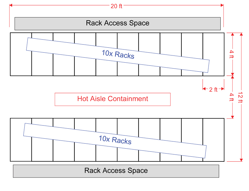
Dimensions of the rack access space and width of an HAC are unique to each data hall design – highly dependent on tenant and location. For example, assume a floor module occupying an area of 16 x 20 feet. Figure 2 illustrates how the racks are organized in the white-space. Depending on the layout, the HAC structure is estimated to weigh up to 2,000 pounds. The raised access floor (RAF) weighs about 12 psf, equivalent to 3,840 pounds over a 16- x 20-foot area.
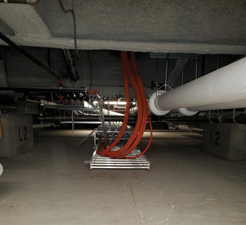
Power distribution unit (PDU) whips are usually installed under the RAFs, introducing a significant amount of weight. Networking cables (LAN or Fiber Optics) could also be installed under the RAF. The occasional maintenance also introduces construction loads, such as a manlift weighing 1,000 pounds. Additionally, a 6-person team occupying this space adds a load of approximately 1,500 pounds. The total of these loads is: 66,000 pounds (rack) + 2,000 pounds (HAC) + 3,840 pounds (RAF) + 3,000 pounds (assumed for PDU whips/LAN cables) + 2,500 pounds (manlift/construction team) = 77,340 pounds spread out in a 16-x20-foot area. This is equivalent to approximately 240 psf, about 60% higher than the minimum specified by ASCE.
Several other factors have not been considered in this design live load, such as the load distribution of a single HAC may be concentrated around a single structure bay, or several utilities are in the space (chilled water, network backbone cabling, main power to PDU cabling). These hanging collateral loads add a significant load on the structure.
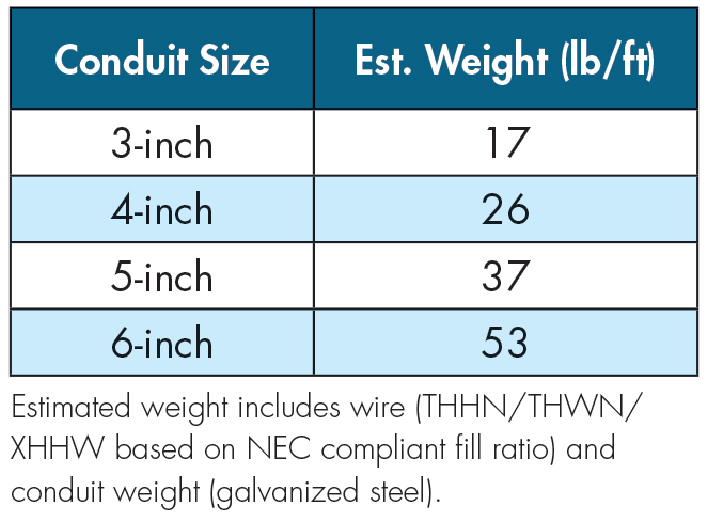
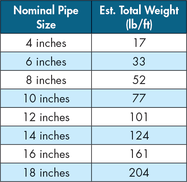
Often, several electrical conduits are run in the same general vicinity since power needs to be routed from the same electrical room or generator room. Table 1 shows the typical weight associated with various sizes of electrical conduits.
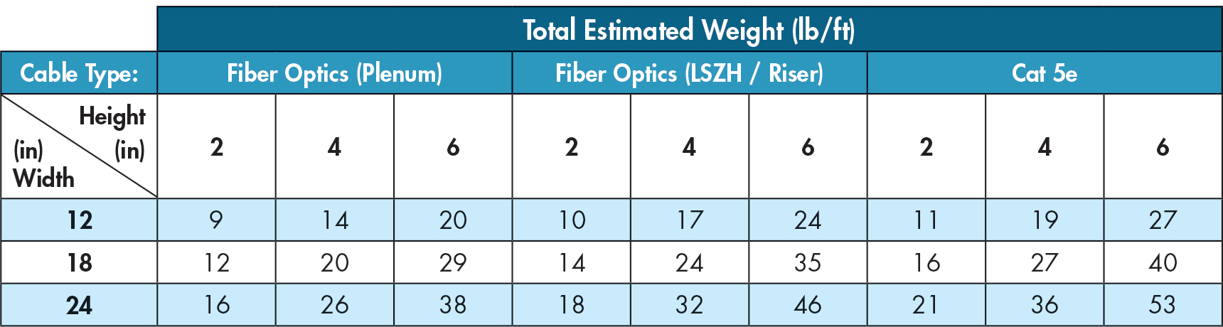
Fiber optic (FO) cables are typically routed from the “Meet-Me Room,” where the network connections from the outside plant (OSP) come into the building and “meet” with the production FO cables for the white-space. Plenum FO cables are likely used in data center applications, but LSZH/riser cables are heavier, complicating the design process. The number of fibers in an FO cable also affects the size/weight of the cable, but lower-count fibers are typically heavier than higher-count fibers (2-fiber cables are “denser” than 144-fiber cables). Table 2 provides a reference for network cable design weights based on the width/height of the cable-tray and cable type (Cat 5e vs. FO).
Several tables are provided in this article to assist with designing these utility supports based on typical standard practice for a data center. For example, Table 3 provides a reference for weights of chilled water lines typically routed through cast-iron plumbing. However, due to the significance of these loads, the structural engineer of record is encouraged to talk with the project’s mechanical and electrical engineer of record to understand how infrastructure utilities are routed throughout the building so the weights of these can be accurately accounted for in the building structure’s design.
Through value engineering, contractors often identify conservative assumptions commonly used in structural design and provide feedback on constructability. Although cost-efficiency is essential to any project, speed-to-market is key in data center projects. IT equipment evolves continuously and quickly. For example, some clients request the racks to be double-stacked, resulting in very high-density white-space. As a result, clients typically prefer a conservative structural design to ensure the capacity to upgrade, when required, is included. In addition, data center facilities undergo significant alterations throughout the project’s life cycle, and the building’s structural design should account for this.
Structural retrofits in a live data center are expensive. Therefore building these potential upgrades into the initial design is much more cost-effective. Since the equipment in data center facilities cannot be exposed to water – very early warning aspirating smoke detection (VESDA) fire-detection systems are installed. When fire alarms are turned off (as required for construction), fire-watch personnel are required. Other considerations for structural retrofits include dust and vibrations that sensitive IT equipment cannot tolerate. Negative air containment is required to contain dust produced by construction projects. Dust can get into the fans and various cooling systems that are crucial for the continuous operation of the IT equipment. In addition, chipping and grinding can produce vibrations outside the vibration limits specified by the IT equipment’s manufacturer. Vibration limits are typically specified as either shocks or random vibration, and operational vs. non-operational. Logically, shock limits should be higher than random vibration since random vibration implies a long duration of an equipment’s continuous vibration exposure. Non-operational is typically applicable when the equipment is in transit.
Requiring that the data center’s operators contract with a structural engineer for every minor modification is not a reasonable expectation. Mechanical or electrical engineers almost exclusively perform maintenance. Structural engineers’ involvement on the operations side is almost non-existent, so oversight of structural items is likely. This introduces operational risks that are undesirable to any data center tenant.
Construction in a live data center introduces various risks, such as vibration, access, dust, and potential property damage from the various construction activities. Due to these risks, clients sometimes occupy/load the top floor of a building first, then use a top-down approach for occupying lower floors. The occupancy of a data center depends significantly on tenants and market conditions; thus, a data center or parts of it may remain vacant for a few years. As structural engineers, we are taught seismic concepts in terms of an inverted pendulum. By loading the data center top-down, the building is the literal definition of an inverted pendulum and will move based on its fundamental mode.
Seismic risk exposure to data centers does not stop at the building. In fact, as indicated previously – data center equipment is sensitive to vibration. Vibration limits of IT equipment can vary broadly. For example, a director switch (IT equipment) has an operating random vibration limit as low as 0.0005 grms (between 10Hz to 200Hz), implying that a person walking on the RAF panel next to the rack can affect the IT equipment adversely. Looking at the shock criteria of the same equipment indicates that the equipment can withstand a 10g magnitude of shock. The intent of the vibration limit is likely to avoid a situation where the IT equipment is placed in a constantly vibrating environment (proximity to fans or in a moving vehicle). Conversations with the OEM uncover that such limits were established based on the tests the equipment has been exposed to (and successfully passed). This differs from a limit typically established in the structural engineering world, where components are tested to failure. It is unclear what exceeding the vibration limit would do to the equipment. CNET published an article where simply “shouting” at the data center equipment can introduce enough vibration to affect latency and impact I/O operations. Due to the complexity of vibration analysis/testing, a common statement from OEMs is that the seismic forces do not impact the equipment, without a clear definition of impact.
Rather than trying to chase the OEM’s vibration criteria, a realistic objective is to design for the stability of the IT racks based on ASCE 7-22 Chapter 13 on Non-structural systems – ensure that it does not overturn from the lateral overturning seismic force. The racks should be braced against the building to minimize damage to its contents. Each of these 2- x 4-foot IT racks is typically valued at $200,000. Therefore damage to a single rack can cause significant monetary loss to the owner.
Damages to structural systems in any facility are catastrophic – a building can be unoccupiable or significant damages to non-structural systems such as power/water systems may occur. Damages to these systems can result in operational downtime. A data center developer trying to design based on Tier III/IV standards would have also completed other risk assessments such as flood risk, air quality, blast risk, tornado, power reliability, etc. In the context of performance-based design: if a data center is to be designed to Uptime’s Tier III or IV standard, then Risk Category IV (Immediate Occupancy / Operational) should really govern the structural design.
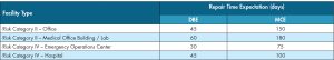
Uptime Tier III’s expected availability target is 99.982%, and Tier II’s is 99.741%. In structural engineering terms, ASCE defines Design Basis Earthquake (DBE) and Maximum Considered Earthquake (MCE) as 10% and 2% probability of exceedance in 50 years, respectively. Table 4 indicates repair time. However, this timeline excludes the time required to identify, plan and permit the work, arrange financing, and hire and mobilize the contractors. For example, at a 50-year return period, repairs must occur within 36 days (for a DBE) and 180 days (for an MCE) to comply with Uptime’s target availability for Tier III. A similar calculation to comply with Tier II requirements yields a 15-month and 79-month repair time for DBE and MCE, respectively.
Another lateral load that is sometimes considered in a data center’s building design is tornado load. Introducing tornado loads into a building’s design may result in the building roof experiencing uplift. Concrete ballasts/topping slabs are sometimes required, introducing a significant dead load to the roof. In this case, it is often better to design for a heavier roof live load criterion rather than the 20 psf minimum required by ASCE. In addition to the overhead utilities mentioned earlier, heavy equipment such as cooling towers, load banks, and water tanks are sometimes located on the roof to decrease land usage. Therefore, it is logical to incorporate the topping slab into the design and get additional roof live load capacity for the project.
Summary
The gravity and lateral load design criteria for data center facilities differ from typical buildings – even Risk Category IV buildings defined by ASCE. Structural engineers play an essential role in the data center facility’s design to ensure the facility’s uptime. Three design objectives typically apply to data center design projects: speed-to-market, scalability, and resilience. Mission-critical data center facilities serve as technological infrastructure that must remain operational after natural disasters, such as earthquakes, hurricanes, tornadoes, etc., to aid disaster recovery and return to normalcy.■