
Designing For Yield Based on Anchoring-to-Concrete Provisions
The American Concrete Institute (ACI) standard ACI 318, Building Code Requirements for Structural Concrete, includes provisions to design cast-in reinforcing bars for development, i.e., embedding a bar deep enough to develop the yield strength without splitting failure occurring. Splitting failure refers to cracking and splitting in the concrete around bars in tension. Post-installed reinforcing bars have typically been designed using ACI 318 anchoring-to-concrete provisions, which consider various possible anchor failure modes rather than designing the bars to yield. This article expands the discussion of a design concept introduced in an ACI Structural Journal article by Charney et al. in which anchoring-to-concrete provisions could be used to design post-installed reinforcing bars specifically for yielding.
What is a Post-Installed Reinforcing Bar?
Post-installed reinforcing bars are installed into hardened concrete. The bars are part of an overall system consisting of the bar, an adhesive product, and the installation method (Figure 1). A hole is drilled into the concrete, cleaned, filled with adhesive, and a bar is inserted into the adhesive-filled hole. After the adhesive cures, any load applied to the bar is transferred into the concrete via bonding between the adhesive, the bar, and the concrete.

Adhesive systems must be evaluated to demonstrate compliance with relevant code parameters. For example, the International Code Council Evaluation Service (ICC-ES) acceptance criteria AC308, Post-Installed Adhesive Anchors in Concrete Elements, can be used to evaluate adhesive systems for design per the International Building Code (IBC) and ACI 318 provisions. Evaluation per the test programs in AC308 Table 3.2 is used to establish parameters for design per ACI 318 anchoring-to-concrete provisions (e.g., ACI 318-19 Chapter 17) and includes reinforcing bars as an anchor element. The test programs in AC308 Table 3.8 are specific to designing post-installed reinforcing bars for development. Adhesive systems that satisfy the Table 3.8 test program can be used to design post-installed reinforcing bars for development with the same provisions as those used to design cast-in reinforcing bars for development (e.g., ACI 318-19 Chapter 25). Adhesive systems that satisfy the AC308 test programs receive an approval known as an ICC-ES evaluation report (ESR). The ESR indicates compliance “in the opinion of ICC-ES” with the model IBC. The ESR contains data and parameters derived from AC308 testing that can be used for design per ACI 318 provisions.
An overview of ACI 318-19 provisions for reinforcing bar development length, and anchoring-to-concrete, is helpful before discussing how anchoring-to-concrete provisions can specifically be used to design post-installed reinforcing bars for yield. In the discussion below, the equation numbers refer to ACI 318-19 unless otherwise stated.
Designing Bars for Development
ACI 318-19 Chapter 25 includes provisions for the development of deformed reinforcing bars (i.e., bars with lug deformations) in tension. The basic equation for calculating the tension development length, ld (in), of a deformed bar is given in Equation (25.4.2.4a):
where:

fy = specified yield stress of the bar lb/in2)
λ = modification factor for lightweight concrete
f´c = specified concrete compressive stress (lb/in2)
ψt = modification factor for casting location
ψe = modification factor for epoxy-coated bar
ψs = modification factor for bar diameter
ψg = modification factor for reinforcing bar grade
db = reinforcing bar diameter (in)
The expression (cb + Ktr)/db is the confinement term. The parameter cb is defined as the lesser of the bar edge distance (measured from the center of the bar) and the center-to-center spacing between bars. The parameter Ktr is defined as the transverse reinforcement index and is defined by Equation (25.4.2.4b):

where:
Atr = area of transverse reinforcement (in2) within a given bar spacing (in)
n = number of bars being developed along the plane of splitting
ACI 318-19 limits the confinement term to a maximum value of 2.5. The commentary R25.4.2.4 notes: “When (cb+Ktr/db) is less than 2.5, splitting failures are likely to occur. For values above 2.5, a pullout failure is expected, and an increase in cover or transverse reinforcement is unlikely to increase the anchorage capacity.” Limiting the confinement term to a maximum value of 2.5 conservatively assumes that splitting failure controls the depth to which a bar must be embedded for development, even when other failure modes, such as pullout, i.e., bond failure or concrete breakout, could control the embedment needed to develop the yield strength of the bar if (cb+Ktr/db) > 2.5.
ACI 318 Anchoring-to-Concrete Provisions
ACI 318-19 Chapter 17 includes provisions for designing cast-in and post-installed anchors with anchoring-to-concrete provisions. These provisions consider various anchor failure modes, which are not contingent on yielding the anchor element. When post-installed deformed reinforcing bars are designed with these provisions, the following tension failure modes are considered: steel failure, concrete breakout failure, and bond failure.
For each tension failure mode, a nominal tension strength, Nn (lb), is calculated and multiplied by a strength reduction factor (φ) to give a design tension strength, φNn (lb). Then, each design tension strength is checked against a factored tension load, Nua (lb).
Steel failure considers the properties of the reinforcing bar. Design steel strength, φsteel Nsa (lb), is calculated for a single bar using the ultimate tensile stress, futa (lb/in2), of the bar instead of the yield stress, fya (lb/in2). Per the ACI 318-19 commentary R17.6.1.2: “The nominal strength of anchors in tension is best represented as a function of futa rather than fya because the large majority of anchor materials do not exhibit a well-defined yield point.”
Concrete breakout failure considers the bar’s effective embedment depth, hef (in), and the concrete properties and geometry. Concrete breakout strength can be calculated for a single bar, φconcrete Ncb (lb), if only one bar is subjected to tension load, or a group of bars, φconcrete Ncbg (lb), if more than one bar is subjected to tension load.
Bond failure considers the edge distance parameter, cNa (in), bar diameter, db (in), characteristic bond stress of the adhesive, τcr or τuncr (lb/in2), and the concrete geometry. The characteristic bond stress of the adhesive is specific to the concrete condition being modeled: τcr for cracked concrete conditions and τuncr for uncracked concrete conditions. Reference the ESR for τcr and τuncr values. cNa is defined in ACI 318-19 as:

where:
da (in) = bar diameter (db)
τuncr (lb/in2) = characteristic bond stress of the adhesive in uncracked concrete
cNa is always calculated with τuncr, even when cracked concrete conditions are being modeled. Bond strength can be calculated for a single bar, φbond Na (lb), if only one bar is subjected to tension load, or a group of bars, φbond Nag (lb), if more than one bar is subjected to tension load.
Design for Yield Based on ACI 318 Anchoring-to-Concrete Provisions
Designing post-installed deformed reinforcing bars for yield based on ACI 318 anchoring-to-concrete provisions seeks to find a solution whereby bars can be embedded at a shallower embedment (hef) than the development length (ld) calculated when only splitting failure is considered (i.e., (cb+Ktr)/db < 2.5). This design approach assumes splitting failure does not control the embedment depth calculation. Instead, it considers anchor failure modes such as bond failure or concrete breakout that might control the embedment, so the design is based on anchoring-to-concrete equations in lieu of tension development equations.
The main premises when designing post-installed reinforcing bars for yield based on ACI 318-19 anchoring-to-concrete provisions are as follows:
- Nominal steel strength, nNsa (lb), is defined as nAse fy (lb) instead of nAse futa (lb) since reinforcing bar design is typically predicated on bar yielding. “n” corresponds to the number of bars assumed to be in tension.
- Nominal concrete breakout strength, Ncb(g) (lb), and nominal bond strength, Na(g) (lb), are calculated for the number of bars that are in tension using the equations given in Table 1.
- Design concrete breakout strength (φNcb(g) lb) and design bond strength (φNa(g) lb) must be greater than the design steel strength, φnAse fy (lb).
Reinforced concrete analysis is used to determine the bar grade and required area of steel, Ase (lb/in2), for the application. The bar diameter, dbar (in), can be determined from this analysis. Once dbar is established, an embedment depth, hef (in) to yield the bar(s), can be determined using anchoring-to-concrete equations. This is a trial-and-error process. The design goal is to be able to obtain an embedment, hef (in), that (a) permits bar yielding instead of concrete breakout and bond failure, and (b) is less than the tension development length, ld (in), predicated on splitting failure.

Reference the equations in Table 1. The parameter Nb (lb) given in the nominal concrete breakout strength equations is the “basic concrete breakout strength of a single anchor.” Nb is defined as follows:

where:
kc,cr = coefficient for basic concrete breakout strength for cracked concrete conditions or
kc,uncr = coefficient for basic concrete breakout strength for uncracked concrete conditions
Reference the ESR for kc,cr and kc,uncr values.
λa = anchoring-to-concrete modification factor for lightweight concrete
f´c = specified concrete compressive stress (lb/in2)
The parameter Nba (lb) given in the nominal bond strength equations is the “basic bond strength of a single anchor.” Nba is defined as follows:

where:
τcr = characteristic bond stress for cracked concrete conditions or
τuncr = characteristic bond stress for uncracked concrete conditions
da (in) = dbar (in) = bar diameter
Since the equations for calculating Nb and Nba include the embedment depth parameter hef, a trial hef-value can be calculated by equating the steel strength of a single bar, Asfy (lb), to each equation and solving for hef.

The trial hef-value can now be used to calculate the nominal concrete breakout strength, Ncb(g) (lb), and nominal bond strength, Na(g) (lb), for the number of bars that are in tension, based on the concrete geometry and bar layout. If the design concrete breakout strength, φNcb(g) (lb), and design bond strength, φNa(g) (lb), calculated with this hef-value are greater than the design steel strength for the number of bars in tension, φnAs fy (lb), bar yielding in lieu of concrete breakout or bond failure has been achieved because the design is controlled by φnAse fy (lb). If either φNcb(g) or φNa(g) calculated with this hef-value are less than φnAsfy, bar yielding in lieu of concrete breakout or bond failure has not been achieved. A new bar diameter and/or steel grade must be selected, and the design procedure repeated. Selecting a new bar diameter and/or steel grade is contingent on first satisfying the reinforced concrete analysis criteria for the connection being designed.
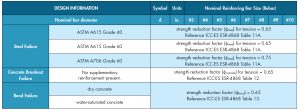
Strength reduction factors (φ-factors) used to calculate anchoring-to-concrete design strengths vary. Table 2 shows steel strength, concrete breakout strength, and bond strength φ-factor values for a post-installed reinforcing bar system.
These φ-factor values are derived from product-specific testing per AC308 Table 3.2 and are used in the checks noted in Table 1. Steel strength φ-factors correspond to whether the anchor element is a ductile element or a brittle element. Concrete breakout and bond strength φ-factors reflect sensitivity to installation parameters such as adhesive mixing, hole cleaning, and concrete conditions (e.g., dry concrete, water-saturated concrete, etc.).
When designing cast-in or post-installed reinforcing bars, the reinforced concrete analysis used to determine bar diameter, grade and layout includes using a φ-factor (e.g., φMn ft-k/ft ≥ Mu ft-k/ft). Since the ACI 318 equation for calculating ld does not include a φ-factor, the anchoring-to-concrete calculations for yield could likewise waive the use of a φ-factor, and the design check would simply be: nAs fy < MIN{Ncb(g): Na(g)}. However, an overstrength factor (e.g., 1.25) when calculating steel strength may be relevant for seismic design (φnAs fy = 1.25nAsfy). Likewise, if a more conservative design solution is desired, the default φ-factors for concrete breakout and bond failure given in the ESR or some φ-factor less than 1.0 could be applied to Ncb(g) and Na(g). The decision to use a φ-factor for anchoring-to-concrete yield calculations, and the value used, should be based on experience, best practice, and approval by the authority having jurisdiction.
Summary
Designing post-installed deformed reinforcing bars for yield based on ACI 318 anchoring-to-concrete provisions in place of ACI 318 development provisions can be summarized as follows:
- Calculate a trial embedment depth, hef (in), by equating the basic concrete breakout strength, Nb (lb), and basic bond strength, Nba (lb) to the steel strength of a single bar (As,bar fy lb). The trial hef value equals MAX {hef,concrete : hef,bond} < ld.
- Calculate nominal concrete breakout strength, Ncb(g) (lb), and nominal bond strength, Na(g) (lb), for the number of bars being designed for tension development using MAX {hef,concrete in: hef,bond in}.

3. Check to see if steel strength controls.

*OK? Design satisfied using selected bar diameter and steel grade.
*NO? Select a new bar diameter and/or steel grade and go to step 1.
Conclusion
The ACI 318 equation for calculating tension development length, ld (in), assumes splitting failure controls and limits the confinement term (cb+Ktr)/db to a maximum value of 2.5. If deformed reinforcing bars are installed such that (cb+Ktr)/db > 2.5, anchor failure modes rather than splitting failure may control the design. This article discussed how anchoring-to-concrete provisions could be used to design post-installed deformed reinforcing bars for yield by considering concrete breakout failure and bond failure in lieu of splitting failure.■
Reference
Charney, A., Pal, K., and Silva, J. (2013). Recommended Procedures for Development and Splicing of Post-Installed Bonded Reinforcing Bars in Concrete Structures, ACI Structural Journal, Vol. 110, No. 3, pp. 437-447.