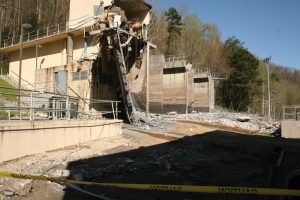
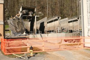
Cain and Associates Engineers and Constructors, Inc. of Mobile, Alabama, were engaged by a Law Firm from Knoxville, Tennessee, to investigate the cause and origin of the collapse of a large Wastewater Treatment Plant Equalization Basin in Gatlinburg, TN. On April 5, 2011, following a period of very heavy rains, the equalization basin at the wastewater treatment plant experienced a catastrophic failure when the east wall of the structure collapsed (Figures 1 and 2). As a result, over one million gallons of wastewater were released. In addition, two employees working in a flow control building located approximately 8 feet in front of the east wall were killed in the incident.
The equalization basin was a 123- by 63-foot reinforced concrete structure with five baffle walls that allowed wastewater to channel through the system. Three baffle walls intersected the east wall, and two intersected the west wall. The structure was 30.5 feet high from the base mat to the top of cantilever walkways on the north, south, and east sides. The structure was constructed using cast-in-place reinforced concrete set in multiple pours. The exterior walls were 18 inches thick, and the baffle walls were 12 inches thick. The total concrete volume above the base mat was approximately 1,100 cubic yards.
The structure, designed and constructed between 1994 and 1996, was placed in service in 1997 and operated until the failure.
Design and Construction of the Basin
It is unclear exactly which design code was used for the original engineering basis. However, analysis of the structure and the as-built conditions indicated that the structure did not meet ACI – 318, Building Code Requirements for Structural Concrete and Commentary, and ACI 350, Code Requirements for Environmental Engineering Concrete Structures. This was the consensus of multiple experts who reviewed the failure.
The design drawings did not indicate any construction joints in the basin other than between the base slab and the walls. Due to the size and complexity of the basin, it was not reasonable or practical that it be constructed in a single pour. The ACI 318 and ACI 350 codes require that construction joints be located and detailed. ACI 350 states that construction joints “should be located so as to least impair the strength of the structure, to provide logical separation between segments of the structure, and to facilitate construction.” This is certainly intended to be a combined effort between the engineer and construction personnel, but it should be initiated in the project’s design phase. In this case, it was initiated in the field based on coordination between the construction superintendent and the engineer’s representative. Reinforcing bar couplers were used to connect the baffle walls to the east and west perimeter walls.
There does not appear to have been any consideration given in the initial design for corrosion or chemical attack. Per ACI 318, Section 1.4.4, Concrete Sanitary Engineering Structures should be designed following ACI 350 to provide higher resistance to chemical attacks and to minimize the possibility of cracking and deflections. In addition, special emphasis is placed on the design and placement of joints. Per ACI 350R-89, factors used for reinforcement in flexure are increased by 30%, and factors for reinforcement in direct tension are increased by 65%. ACI 350R-89 requires that joints be shown on the design drawings and that joints should be placed so as not to impair the strength of the structure. ACI 350 also addresses the importance of concrete quality.
The ACI 350 code specifically addresses exposure to corrosive liquids, and that allowable loads are based on the premise that reinforcing steel will be in contact with those liquids. This is one basis for this code and a major factor in justifying the use of ACI 350 and the additional costs that this would entail.
Operational and Maintenance History
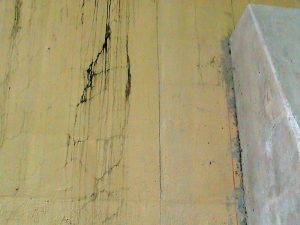
Shortly after the basin was placed into service, the north wall began to bow outward by approximately 4 inches during a very heavy rain period. At that time, the tank level was reported to be approximately 26 feet. This was well above the normal operating level of approximately 10 feet. The resulting lateral displacement caused cracks to form in this wall and the perimeter walkway (Figures 3 and 4).
An engineering study was initiated to determine the cause of the bow and design a fix. During this process, it was determined that the reinforcing steel design of the north wall did not meet the requirements of the ACI 318 code and the more stringent ACI 350 code. It was speculated that the ACI 350 code might not have been used because it would have significantly increased the project’s overall cost. However, this was never determined to be the case.
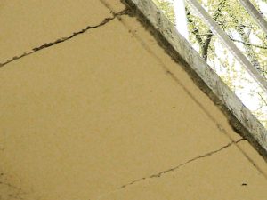
The study did indicate that the deflection and the resulting cracks were likely caused by the ends of the 63-foot-long north wall acting in a pinned-pinned condition rather than a more rigid fixed-fixed condition. Further, the walkway that ran the entire length of the north wall and that extended 4.5 feet from the face of the wall appeared to be acting as a horizontal stiffener beam. This was most likely not the intent of this element; however, its presence most likely lessened the observed displacement caused by the high water levels.
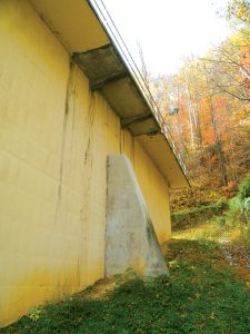
Modifications were made to the north wall of the structure. They included the addition of an exterior buttress (Figure 5) and a recommendation to limit the water retention height in the tank to 26.5 feet. The buttress was installed, but there was no indication that level control systems were installed.
At the time of this initial failure and subsequent investigation, it appears that the review and analysis were limited to problems associated with the north wall. In retrospect, a complete analysis should have been performed based upon the complexity of the problems and the obvious under-design of the structure.
Failure of Basin and Subsequent Investigation
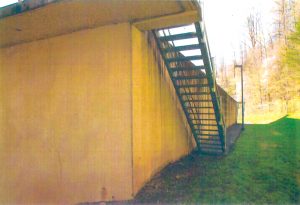
On April 5, 2011, following very heavy rains, the east wall of the basin collapsed in a catastrophic failure resulting in two fatalities. At the time, it was reported that the basin was filled to a depth of approximately 26 feet. The basin was constructed without overflow structures, and there was evidence on the outside of the west wall that the basin had overflowed before the failure (Figure 6).
Cain and Associates performed an analysis of the original design. They indicated that the design did not meet the requirements of ACI 350 but also did not meet the requirements of ACI 318. Additionally, several other deficiencies were noted from the original design regarding the detailing and construction of the basin.
Finite element analysis was performed on the basin, which determined that, at full water depth, the north wall reinforcing steel was underdesigned by up to 113.35% per ACI 318 and by up to 177.35% per ACI 350. Similarly, the east wall reinforcing was underdesigned by 127.96% per ACI 318 and by up to 196.34% per ACI 350. The authors consider the analysis using a depth of 30.42 feet reasonably based on evidence that the basin had overflowed in the past. Additionally, independent analysis by other professionals determined that the limiting depth of water in the basin would have been 21 feet per ACI 318 and 17 feet per ACI 350.
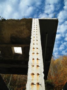
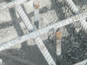
Reinforcing bar couplers were used to connect the baffle walls to the east and west walls of the structure (Figure 7). The couplers were similar to a Dayton D50 – #5, product code 77100. Cain and Associates calculated the maximum tensile force in a pair of couplers attaching the baffle walls to the east wall to be approximately 43 kips at the height of approximately 9.5 feet above the basin floor. The load at yield for a pair of threaded #5 bars is 27.12 kips based on a yield stress of 60 ksi and a cross-section area at the cut threads of 0.226 in2. The required ultimate design strength should have been no less than 70.95 kips based on the calculated load of 43 kips and the direct tension factor of 1.65 as defined in ACI 350.
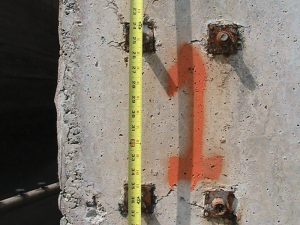
There was some evidence of corrosion of the couplers, but this did not appear to be a significant factor in the failure. Instead, the overstress of these members, cyclical loading, and resulting fatigue over the structure’s life were more likely contributing factors to the failure (Figures 8 and 9). In addition, the placement of the couplers was such that the threads could not be fully engaged at some locations due to the proximity of the adjacent hooked bar.
The north wall was also analyzed from a crack control standpoint. To control deflections and cracking, both ACI 318 and ACI 350 place a limit on a crack control factor known as the Z factor. These limits are 145 kips/inch and 115 kips/inch, respectively. Analysis of the north wall support determined that the Z factors ranged between 209 kips/inch and 362 kips/inch depending on location and water depth in the basin. These fall outside the acceptable range and support the conditions observed during the initial failure of the basin in 1997.
It is more likely that the ultimate collapse of the east wall was caused by the tensile failure of the reinforcing bar couplers. Once the initial failure occurred, a subsequent instantaneous chain reaction failure was caused by the transfer of loads to adjacent couplers.
Conclusions
The authors’ opinion is that the structure’s failure was primarily due to three significant factors. Initially, the structure was not designed to the correct code, which allowed for significant reductions in construction costs, although it is unclear that this was the motivating factor. The correct design code should have been ACI 350, and this, when properly followed, would have provided a much more robust structure than what was constructed. The second contributing factor was the fact that there was insufficient information provided on the design drawings regarding joint locations and designs. These are required by code to be shown on the drawings, but the absence of this information forced decisions for joint locations to be made in the field. This was facilitated by coordination between the contractor, owner, and engineering representative. The location and design of the joints between the baffle walls and the exterior perimeter walls were inferior and significantly contributed to the collapse. Lastly, there were issues with the basin that occurred during the operational period. However, these were not adequately addressed. Horizontal displacement and cracking issues associated with the north wall were significant and should have been a harbinger of future problems. Although modifications were made to lessen the detrimental effects occurring in the north wall, it was also noted at the time that the structure was inadequately designed to not only ACI 350 but also ACI 318. Once this was determined, a more thorough structural analysis of the constructed conditions should have been undertaken, which may have resulted in the removal of the basin from service.■

