
Adaptive Reuse at All Hallows School
The historic All Hallows School is an all-girls secondary school located in Brisbane, Australia. Founded by the Sisters of Mercy in 1861, All Hallows is the oldest secondary school in the state.
Over the years, Brisbane has transformed from a small penal colony formed in 1824 to the third-most populous city in Australia. As the city grew, with high-rise towers now casting their shadows over the campus, so did All Hallows School. The campus has evolved with contemporary architecture seamlessly integrating with the original heritage-listed structures. The Exchange Building continues this legacy by combining environmentally sustainable design with inspirational learning opportunities.
The Concept
All Hallows School identified a need for additional space for their staff and students. But as real estate was limited in this historic, inner-city campus, they looked to their well-loved library, the Potter Building, to provide the required area. The needs included a senior study center, IT support services, offices, a variety of modern teaching and collaboration spaces, and a rooftop function area.
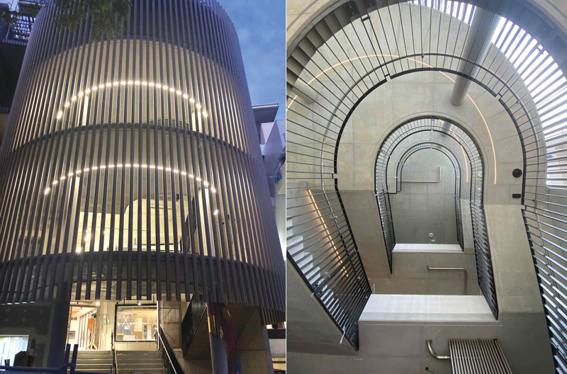
Fulton Trotter Architects were tasked with the challenge and developed the concept of The Exchange Building. The scheme utilized large internal voids and interconnecting stairs to create fluid, interconnecting volumes, with two new external stairs providing a vibrant focal point for the building. The Potter Building would require wide-ranging modifications, extensions, and demolition to achieve the architectural vision.
Existing Structure
The original Potter Building was constructed in 1972, consisting of a three-story concrete framed structure with unreinforced brick infill and a brick stair core to the western end. In 1978, the building was extended with the addition of another floor. However, once the contractor was on-site and began peeling back the layers, it became evident that the building was subjected to numerous structural modifications over the decades that were undocumented, increasing the challenges involved with retrofitting the building.

The original building framing was typically 36-inch-deep × 21-inch-wide reinforced concrete beams running north-south at 16.5 feet on-center, supported by 16-inch-square columns. The typical slab was four-inch-thick reinforced concrete. Level two was the lowest suspended level of the four-story building, with plan dimensions of approximately 180 feet × 82 feet. The building stepped at the eastern end, with reduced floor plate dimensions of approximately 141 feet by 52 feet for levels three and four.
Site Challenges
The site was heavily constrained as it was in the middle of an active schooling environment with numerous buildings surrounding it. Access to the site is also extremely limited, with only two means of approach:
- Along a narrow laneway to the west, entered via a heritage-listed and protected stone archway. Not only would the risk of damaging the archway with its limited head height be enormous but, to further complicate matters, the arch is accessed from Ann Street, a very busy, one-way, major four-lane thoroughfare through Brisbane. Obtaining road closure permits from Brisbane City Council would be difficult and expensive.
- Through a much wider and more accessible entrance to the North. Unfortunately, this entrance also has its limitations as larger construction vehicles cannot make it to the site due to an overhead pedestrian link bridge with limited head clearance located along the route.

To Demolish or Not to Demolish
The proposed scheme involved extending the largest floor plate at level two and significantly extending the floor plates above to create a consistent area for each floor of the building, with the original building to the west remaining largely untouched. Finally, an entirely new floor was to be introduced.
Early schemes considered a traditional structural system of new reinforced concrete (RC) walls and columns with post-tensioned (PT) flat plates. However, as the design progressed, it was determined that existing columns and footings would require strengthening to accommodate the heavier structure. Alternatively, the entire existing building within the footprint of the new development would need to be demolished and re-built.
In addition, the very restricted laydown and working space of this site placed significant restrictions on a conventional solution of in-situ concrete framing. Therefore, prefabrication and weight were two primary considerations that drove the final structural solution.

Bligh Tanner, the Structural Engineer for the project, proposed a lightweight Cross Laminated Timber (CLT)/steel hybrid structure to limit the additional weight applied to the existing structure. The hybrid system consists of CLT panels supported on steel beams, with the panels connected to the beams by screwing through pre-drilled holes in the steel flange from below. The lightweight system allowed footings and columns to be reused without expensive and disruptive strengthening. The reduction in weight also meant lower seismic demand, and therefore fewer bracing walls were required, allowing for more uninterrupted spaces and greater future flexibility. It also enabled the majority of the existing floorplates to be retained. A hybrid CLT/steel system was adopted as the original structural grid determined the new column positions. The resulting spans were too large for an entire mass timber solution to be economical.

The CLT and steel system also assisted with the site access and storage constraints. The prefabricated elements could be delivered to a laydown area off-site as required and lifted into place with a single tower crane. The CLT and steel construction resulted in less dust, noise, and workers on-site. In addition, it eliminated the queues of concrete trucks, which would be required for large concrete pours and, therefore, significantly reduced the general disruption to the school. However, in-situ concrete was still utilized for new footings and to form a complex cylindrical Drum structure for the external stairs and new shear walls to the front of the site as the complex geometry was better suited to the flexibility of concrete. Pre-cast concrete panels were also adopted at the back of the site to form a bracing wall. The panels were cast in lengths to suit the tower crane lifting limits with their vertical edges stitched together with steel plates field welded to plates cast into the panels.

Strengthening
Where the existing structure was being altered or the design loads increased (for example, where an internal span became an end span due to demolition), carbon fiber was provided to strengthen the structure without impacting floor-to-floor heights or service routes. Strengthening consisted of pultruded carbon fiber reinforced polymer laminates bonded to the soffit and top side of beams and slabs. Several beams were also strengthened for shear with sheets of unidirectional stitched carbon fiber fabric. In one case, where the post-demolition deflections required a higher degree of control, a beam was instead strengthened by providing a steel beam below and pre-loading the beam with a flat jack to take over the dead load acting on a concrete beam. Once the new steel beam had taken the load, the space between the steel and concrete was packed with steel shims and grouted. The adjacent span of the concrete beam was then able to be demolished.
Footings
The original building footings were investigated and confirmed to have been founded on strong rock. The lightweight hybrid solution allowed the existing footings to be maintained. Pile caps and ground beams with micropiles were adopted for the new building’s vertical and bracing elements. Micropiles were chosen due to head height restrictions as a small rig could be used to install the piles. This resolved the site access and head height constraints. Plan dimensions for the pile caps and ground beams could also be kept to a minimum, reducing the amount of excavation required and potentially undermining adjacent existing footings. Micropiles could also efficiently resist the uplift forces under the new bracing elements.
Construction Surprises
Several surprises were uncovered once the contractor, KANE Constructions, was established on-site and began to strip the existing building finishes. Those surprises included a previously assumed slab on grade being suspended over a crawl space and old floor voids filled with sections of concrete slabs cast on metal deck. It was also discovered that one of the floor plates had been extended previously, with an additional bay being added. It was determined that an external beam that would have previously been a gable end beam supporting brick cladding was, at some stage, turned into an internal beam. Additionally, the floor levels had been raised not once but twice on the same floor, with two distinct layers of topping uncovered, totaling six inches. Consequently, the design needed to be revisited as the assumption of an eight-inch slab and 36-inch beam was incorrect. The beam depths on this floor were six inches less than previously assumed, and their loads had already been significantly increased.
Two of these beams showed signs of distress with flexural cracking at their midspan. The beams were propped, GPR scanned, and concrete removed locally to confirm reinforcement sizes. It was determined that the bars had not yielded, and the beams’ capacity was sufficient to continue strengthening as planned once all cracks had been epoxy injected. Steel dowel bars were also drilled and epoxied vertically from the top surface and into the beam to allow composite action between the topping and the beam.
The successful delivery of this complex and adaptive reuse project has delivered additional space and functions for the original Potter Building while minimizing the impact of new construction on the environment and saving a lot of construction waste going to landfills. Completed in June 2022, the new Potter Building will be the first education building in Queensland constructed using a hybrid CLT/Steel system.■