Renovation and Vertical Expansion Breathes New Life into 633 Folsom
Built in 1967, the original building at 633 Folsom Street in San Francisco was developed by The Swig Company as a modern office building for the telecommunications giant AT&T. Fast forward to the 2010s: AT&T had long since moved out of the space, and the aging midrise building was no longer attractive to tenants looking for a corporate home in San Francisco’s South of Market (SoMa) district. So instead of selling the outdated building or redeveloping the site with new construction, Swig saw an opportunity to give the building a facelift, nearly double its square footage and height, and make it the star of their portfolio. The vision for the new building included a vertical expansion of the existing structure wrapped in a striking new skin. To make this distinctive concept economically feasible required a dedicated design and construction team capable of an equally unique approach.
Challenges Call for a Courageous Solution
The vertical expansion itself posed several significant design challenges. To compete with newer office buildings, the new floors would need to offer long-span, flexible workspaces, much wider than the 20-foot column grid in the 60-year-old structure. At the lower levels, the existing floor-to-floor height left little room for new mechanical systems, let alone any structural strengthening. In addition, the building’s engineering was outdated, particularly with respect to modern seismic detailing. Finally, assessing the new structure was complicated by the multiple layers and eras of construction. After careful consideration, the design team met these challenges by thoughtfully reimagining a new structural layout and designing efficiencies afforded by a performance-based approach using nonlinear response-history analysis.
Innovative Structural Approach
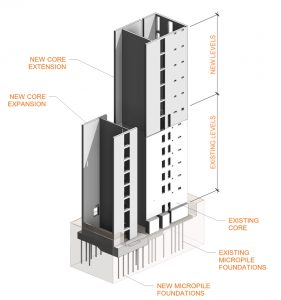
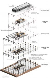
Doubling the height and square footage of an existing building is not trivial from a structural perspective. Before conceptualizing the new design, Tipping, the structural engineer for the project, had to fully understand the existing structure and architectural program constraints. The structural design had to consider these limitations in framing and walls to support the expansion (Figure 1).
The building consisted of two-way lightweight concrete slabs supported by normal-weight concrete columns and ten-inch-thick normal-weight concrete core walls. The columns were supported by spread footings and the central core walls on a mat slab. The original lateral system comprised concrete moment frames around the perimeter and concrete shear walls at the core. In the mid-1990s, a voluntary seismic retrofit was performed to strengthen the existing core walls and mat foundation. A twelve-inch-thick layer of shotcrete was overlaid on four existing concrete walls above grade. Meanwhile, micropiles were added to abandoned basement hallways and repurposed as anchor blocks to provide additional overturning resistance.
The vertical addition called for an expanded elevator-and-stair core adjacent to the original building’s vertical circulation core. This became the natural location for new concrete shear walls, adding strength and stiffness to the existing floors (Figure 2). The core expansion was designed to be independent of the existing core without coupling beams connecting the two. Coupling would have required intrusive and costly structural detailing with relatively little benefit to structural performance. Consequently, the addition of collector elements was required at the existing floors to engage the new core walls under seismic loading. To maximize ceiling height and avoid conflicts with MEP routing, carbon-fiber-reinforced polymer (CFRP) was applied to the top of the slab to complete the load path from the existing diaphragm to the new core walls.

The existing core walls were vertically extended to gain lateral support at the new floors. The upper story of existing walls was demolished to lap existing with new reinforcement over the story height, providing flexural continuity. An analysis of structural response largely drove this solution. Due to better alignment between centers of mass and rigidity, extending the existing core walls to the new roof produced less torsional response than extending the new core expansion to the roof.
Architectural project goals drove the framing layout of the upper floors. Existing perimeter columns had a built-in mechanical chase that was rendered obsolete by the building redesign. Tipping recognized an opportunity to repurpose the chase as an infill concrete column that would support new wide flange columns, thereby minimizing impact to floor space at the existing stories. The structural engineering team laid out the framing to maximize the span from perimeter columns to core walls, reducing the number of interior columns and creating a more flexible space. As a result, only 8 of the remaining 24 existing interior columns were employed to support the building’s new floors. Moreover, the new floor framing layout minimized the architectural impact of column strengthening at the existing floors and mitigated the high cost of foundation strengthening.

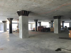
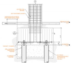
Existing interior columns supporting new floors received a six-inch-thick shotcrete jacket to increase gross area and confinement. All other interior columns were wrapped in FRP to increase ductility. Lastly, steel collars were added around the columns below the existing lightweight concrete slab to address the potential of slab punching around the columns in a seismic event (Figure 3). All columns with added load required foundation strengthening (Figure 4). Owing to the congested site, all perimeter footing retrofits required an offset pilecap with eccentric piles.

Analysis Validates Atypical, Lean Design
The vertical expansion of the building added square footage and new stories, which triggered a complete code upgrade to ensure that all new and existing structures satisfied current code requirements. While early schemes for seismic strengthening of the vertical addition were based on elastic analysis, Tipping relied on a performance-based approach, using nonlinear response history analysis (NLRHA) to justify the final structural design.
The structural engineering team determined that NLRHA delivered the optimal solution for 633 Folsom. The lateral system is atypical, comprising construction from three different eras. Because both material and geometric nonlinearity influence holistic structural behavior, the design relied on careful modeling of all material properties and elements of the lateral force-resisting system. Expected material properties were accounted for in the NLRHA, whereas a response spectrum or equivalent lateral force analysis would have dictated that only nominal properties were considered. By taking advantage of expected material properties using a performance-based approach, the designers could account for the existing structure’s inherent strength and contribution to the overall building response. This approach was key to minimizing the strengthening required for the existing structure and the new elements.
The lateral analysis was conducted with Perform 3D. Wall fiber sections were used to model concrete and shotcrete shear walls. Existing perimeter moment frames were modeled with flexural hinges at beam ends, while the columns were modeled to be elastic. Separate calculations confirmed that the columns did not exceed their nominal moment strength under the maximum force demands from the analysis. The designers accounted for soil-structure interaction at new and existing mat slabs by modeling a grid of beams spanning to soil springs and micropile elements. Rigid diaphragms were assumed at all floors, and explicit collector elements delivered seismic load to the core walls. All gravity columns were modeled as pinned-pinned columns with dead loads on them to capture additional P-delta shear during an earthquake.
Observing and considering the building’s specific response provided insight into where additional strengthening was necessary. Allowing for some yielding and applying displacement-based instead of strength-based acceptance criteria helped minimize the impact on the existing building and the project budget. Further, the team modeled soil-structure interaction, softening the response and lowering the demand compared to a fixed-base building. Early phases of design called for the new core expansion to extend the full height of the building. The nonlinear analysis model validated the approach for new shear walls to extend upwards from the existing core only, while also removing one wall from the initially proposed core expansion. Savings in cost and materials were also made at the foundation of the core expansion, reducing the initially planned number of micropiles at the new mat foundation by more than half, from 34 to 16.
Performance and Value
Renovating and vertically expanding 633 Folsom demonstrates that undesirable, obsolete buildings can be significantly transformed, delivering a high degree of performance and value through thoughtful analysis and design. Public response to the transfigured structure has been overwhelmingly positive: the tech company Asana leased the entire building as its new headquarters before construction was complete. In addition, the project received a 2021 Structural Engineers Association of California (SEAOC) Excellence in Structural Engineering Award. Performance-based engineering and a collaborative process among the design and construction team reinvented the building, which again inspires its users and contributes to a vibrant community.■

