
Part 1: Design Process
San Francisco’s Pier 70 is located on the city’s southern waterfront on the San Francisco Bay, an area with a rich history of industry and shipbuilding dating back to the 19th century. Over time, these uses diminished, and many of the buildings fell into disrepair. In 2015, the Port of San Francisco began plans to redevelop the area around Pier 70 to create up to one thousand housing units and two million square feet of office space.
Building 12 is a large and prominent building constructed in 1941 with two tall stories of riveted steel framing and wood plank floors and a roof supported on long-span trusses. With tall and wide crane bays, the first floor was used for building ship hulls. The upper floor, called the “mould loft,” was used to build the wooden formwork (molds) around which the steel plate hulls were shaped. The 240-foot-wide building had only two interior lines of columns, with floor and roof spans of 50 to 100 feet. The building’s roof has a distinctive “square sawtooth” profile with vertical clerestory windows on the north and south sides of each sawtooth, providing natural light at the loft.
The renovation project raises the entire building off its original foundation by 10 feet to add a basement parking level and a partial 2nd floor under the mold loft, which becomes the third floor. In addition, the building is retrofitted with new buckling restrained braces, floor diaphragms, and collectors for seismic and wind loads. The renovations maintain the historic and industrial feel of the building while creating a modern space for commercial tenants.
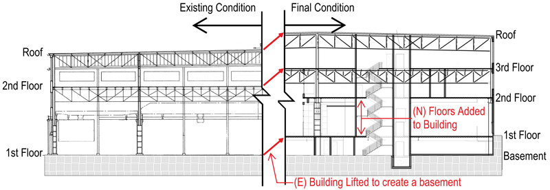
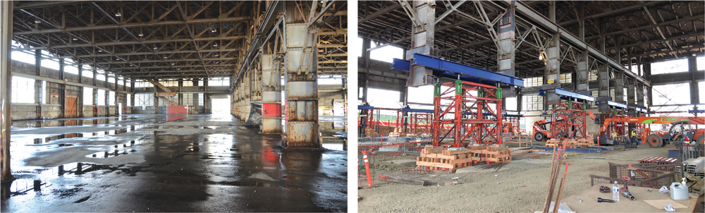
The two added floors nearly double the building’s square footage. After the building construction, including the lift of 10 feet to create a new bottom story, 10 feet of fill was added to the entire locale to protect the area against sea-level rise and make the new bottom story a below-grade basement. The lifting of the building required 66 columns to be jacked up simultaneously in small increments over 7 days (Figure 1). A separate article dedicated to construction engineering (shoring, temporary bracing, and lifting) will be published in a future issue. A building section before and after the lift is shown in Figure 2.
Existing Structural System
The existing roof and 3rd floor are wood sheathed floors supported by steel beams that span to 7-foot-deep steel trusses that vary in length from 50 to 100 feet. The new 2nd and 1st floors consist of a new slab-on-steel deck over steel beams. Additional lines of columns were added in the new framing to break up the 100-foot spans. At the basement, new steel columns support the lifted existing columns. The entire perimeter of the basement has a concrete retaining wall. All of the existing footings were replaced with new footings and grade beams. The existing building lateral system consisted of tension-only angles, column knee braces, and a truss moment frame (the bottom chords of the long span trusses connect to the existing columns).
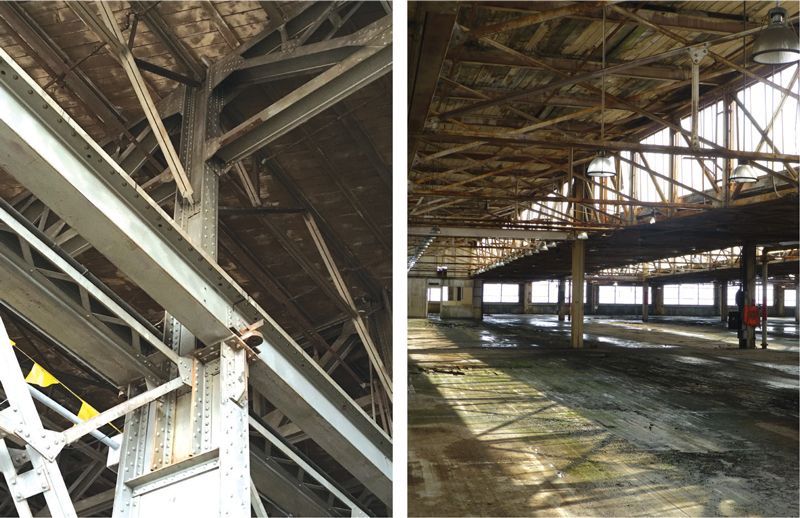
One of the project’s most significant challenges was a lack of existing structural drawings. Detailed site investigations were conducted to confirm the sizes and connections of the long-span trusses, built-up steel columns, and wood flooring. Figure 3 highlights the complexity of the existing construction. Luckily, all of the structure is exposed, but it required special equipment to get close enough to determine member sizes by hand with a tape measure. Material testing consisting of yield strength testing and weldability analysis was performed on the steel elements to validate design assumptions.
Due to the lack of existing documents, the project team elected to do a 3-D scan of the building to better define existing elements in the architectural model. The scan indicated that the existing columns were all slightly off (fractions of an inch) from the straight grid lines. The design accounted for these discrepancies prior to construction. After the design was complete and construction began, the building was lifted. When the columns were resurveyed after the building lift, it was found that they had shifted from the original 3-D scan up to 2 inches in the worst locations. This generated numerous special conditions in the project: 1) basement wall reinforcement had reduced clearances, 2) column base plate anchors were out of place, and 3) steel beam bolt holes did not align with column shear tab holes. The design and construction team learned that when lifting or moving large structures, designs should account for these tolerances and, where possible, the connection details should allow for field adjustments. The contractor should survey the column locations after the structure has been moved and incorporate those into the shop drawings. More discussion on construction tolerances will be included in Part 2 of the series.
Seismic Analysis and Retrofit
The project considered using a non-prescriptive seismic design with nonlinear response history analysis (NLRHA) instead of a code-prescriptive design. This would improve the understanding of seismic performance and reduce brace sizes by explicitly accounting for the truss moment frame. The downsides were that it added design costs and triggered a seismic peer review. While the savings associated with reduced member sizes could offset the additional design fees, the peer review would add an additional step to the approval process, creating a risk to the schedule. The project ultimately decided on a prescriptive design.
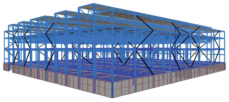
A three-dimensional finite element model was built using SAP2000 (Figure 4) and included gravity elements that contributed to the building lateral resistance (i.e., large steel trusses). A two-stage linear dynamic response spectrum analysis was used to design the retrofit. The flexible upper portion of the structure is a buckling restrained braced frame (BRBF) system with a code-prescriptive value of R = 8. The rigid lower portion of the building is a special concrete shear wall system designed for overstrength loads from the BRBF system. All floor diaphragms were modeled as semi-rigid with appropriate properties for timber roof, timber floor (3rd floor), and slab over steel deck (1st and 2nd floor).
Drift compatibility created a problem for the design. Even though the BRBs are designed to resist 100% of the lateral load, forces develop in the existing gravity trusses and columns as the building drifts. The project team explored removing the bottom chord at the column to create a pinned condition, but this resulted in excessive deflections. The final design imposed the drifts on the truss frame analysis model and retrofitted the truss where excessive forces occurred. Three models were used to design the building. The first model included gravity elements that resisted lateral loads to determine the drift compatibility forces in the existing trusses and columns. The second model “zeroed out” the stiffness of gravity elements so 100% of the load went to the BRBF system. This model governed the BRB design. The last model applied overstrength factors (BRB upper bound axial capacity divided by the design axial demand) to design collectors and expected brace forces.
Structural Detailing
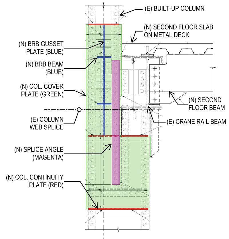
The existing built-up columns created challenges for detailing the BRB connections, particularly at the location of the existing crane beams, which occur near the added 2nd floor and complicate the geometry. Figure 5 shows a typical condition at the second floor. The BRB gusset plate (orthogonal to the two-dimensional drawing) is centered on the upper column, which is offset from the centroid of the lower column. Horizontal continuity plates were placed above and below the BRB gusset plate. Vertical cover plates were welded across the existing column’s flange tips and also welded to the continuity plates. The column cover plates and added splice angles were designed to transfer loads between the offset column flanges and provide continuity for the maximum forces that the braces could deliver.

The third-floor assembly, shown in Figure 6, also presented detailing challenges:
- The 2x diagonal plank flooring of the original mold loft, viewed from the underside, had historical and architectural value that needed to be maintained,
- 1.5 inches of gypcrete was needed to satisfy acoustic requirements, and
- New 2x tongue and groove (T&G) sheathing and plywood were required for the new vertical design loads and the floor diaphragm’s seismic force path. The new 2x T&G sheathing on top of this floor system makes an architectural statement in the sky-lit space of the former loft. Although it is not placed diagonally like the original plank flooring, it reflects the original materials at the loft.
Special design considerations and detailing were needed. Thicker plywood was used to ensure field nailing did not penetrate through the existing sheathing and be visible below. Boundary nails were not long enough to transfer lateral loads directly to the steel beam nailer, so two sets of boundary nails were required. One set was from the plywood to the diagonal sheathing and another from the diagonal sheathing to the nailer, which was attached to the steel beam with welded threaded studs. The diagonal sheathing was not parallel to the plywood edges. The contractor carefully coordinated plywood nails to avoid gaps between existing sheathing.
Conclusion
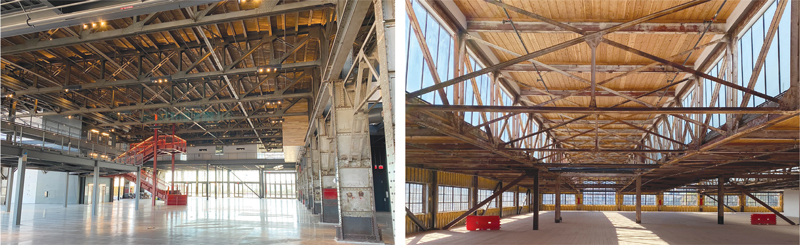
This project was a great success. The design, lifting, and construction teams worked through challenging as-built conditions that literally moved during the course of the project. The final product (Figure 7) showcases the simple beauty of structural engineering for all to see. It also allows the continued use of this building while celebrating a piece of history.■
Project Team
Owner: Port of San Francisco
Developers: Brookfield Developers
Structural Engineer: Nabih Youssef & Associates
Structural Engineer Sub-Consultant (lateral system design): Maffei Structural Engineering
Architect: Perkins & Will, Pfau Long
General Contractor: Plant Construction