
To Top Rail or not to Top Rail
The engineering of guardrails has generally been straightforward ever since they were first addressed in building codes. Even the earliest building codes, like the Uniform Building Code (UBC) and the Building Officials and Code Administrators’ (BOCA) National Building Code, had live load requirements for typical handrail and guardrail scenarios.
Historically, the building codes addressed guardrails under the assumption that they were fabricated metal pipe or metal tube assemblies that provided fall protection for any walking surfaces greater than 30 inches above the surface below. Standard two-line metal pipe railings have been used for decades in industrial settings, and ornamental metal railings are used to this day as architectural features for buildings around the world. It is common for these typical metal railings to see a minimum code-required 200-pound concentrated live load and a separate 50-pound-per-foot uniform load case applied at the top of the guard. Often, an additional 50-pound load applied over one square foot of the infill of the guardrail was required if the guard was functioning as a decorative railing in a residential or commercial setting.
In the mid-1900s, the architectural world started to move toward glass as a desirable construction material, and the development of the glass balustrade guardrail was introduced. The first patent for a structural glass balustrade shoe was issued in 1967, and they have increased in popularity exponentially since the 1970s and 1980s. Changing times also means changing codes, and since glass behaves so differently than metal, this new structural glass balustrade needed to be addressed. The 1988 edition of the UBC was the first mainstream code to address glass railings, and the requirements introduced in this code laid the groundwork for the requirements found in the current editions of the International Building Code (IBC).
The 1988 UBC addressed glass strength requirements, safety glazing testing, and precautions to include if a glass panel breaks. In addition, this code noted an interesting requirement for a glass balustrade guardrail: “Glass balusters shall not be installed without a handrail or guardrail attached.”
This one requirement has provided much debate in the glass railing industry and certainly has caused a few headaches for engineers, glass railing manufacturers, building owners, and architects over the past 10 years. This article focuses on this code requirement and how changes in the code over the last decade have resulted in some significant structural issues and a new glass testing procedure required in the 2018 edition of the IBC. The terms top cap and top rail are used interchangeably throughout the article.
Glass Railing Code Requirements
As mentioned above, handrail and guardrail live load requirements in the most recent governing building codes (OSHA, ASCE, IBC, etc.) have all essentially remained the same as summarized in IBC Chapter 16, Section 1607: 200-pound concentrated load and a separate load case of 50-pound-per-foot uniform load applied perpendicular to the top of the guard. Additional code requirements for glass railings can be found in IBC Chapter 24, Section 2407, Glass in Handrails and Guards, including (emphasis added):
2407.1.2 Support. Each handrail or guard section shall be supported by a minimum of three glass balusters or shall be otherwise supported to remain in place should one baluster panel fail. Glass balusters shall not be installed without an attached handrail or guard.
These requirements in IBC Chapter 24 are essentially the same as the first glass railing requirements introduced in the 1988 edition of the Uniform Building Code. The code is unclear as to what constitutes an “attached handrail or guard,” but it is generally assumed to refer to a rail section on top of the glass baluster, otherwise referred to as a top cap.
Starting with the 2009 edition of the IBC, an exception to the glass baluster top cap requirement was introduced and is noted in IBC 2009 Section 2407 as (emphasis added):
Exception: A top rail shall not be required where the glass balusters are laminated glass with two or more glass plies of equal thickness and the same glass type when approved by the building official. The panels shall be designed to withstand the loads specified in Section 1607.7.
The International Code Council (ICC) further explained this “exception” in their published commentary by stating the following:
The exception allows an option where a top rail is an undesirable visual barrier. An example is a guard at the front of the spectator levels of sports arenas and theaters. The balusters must be laminated glass complying with the live load requirements for guards and handrails.
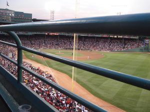
Based on the ICC’s explanation of the exception introduced in the 2009 IBC, the intent was to provide for unobstructed viewing of a special live event, such as being able to watch your favorite baseball pitcher throw a perfect game (Figure 1) or to see the play “Hamilton” without a top rail running through Alexander’s head. Two essential qualifications must be met to install a glass railing without a top cap: 1) the glass must be laminated, and 2) the railing without a top cap must be approved by the building official.
However, from 2010 onward, manufacturers and architects seem to take advantage of this top cap exception and apply it to all types of glass guardrails, regardless of the application or if there really is a viewing event. Currently, high-rise balconies, rooftop windscreens, amenity terraces, and other typical building guardrails, including lobby/monumental stairways, are being planned without a top rail or top cap. The code relies on the building official to decide whether or not the guardrail application can use this exception, but that approval procedure does not seem to be happening. Otherwise, in the author’s practical opinion, a monumental stairway in a hotel lobby would not be considered an event-viewing venue, and the glass guardrail would require a top cap.
Base Shoe Railings and Point-Supported Railings
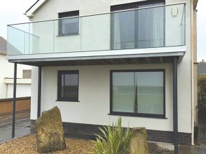
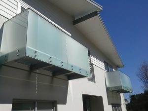
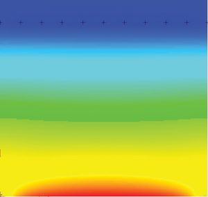
The IBC is also unclear on what type of glass railings the top rail exception should apply. Structural glass balustrades typically have two configurations for attaching to the host structure. Figure 2 shows an example of a base shoe style railing, and Figure 3 shows an example of a standoff style or point supported glass railing. It is important to differentiate the two attachment methods because glass behaves differently when point-supported than when secured in a base shoe. Base shoe supported glass allows structural design loads to distribute evenly as bearing stress along the bottom face of the glass that is captured within the shoe. Figure 4 shows how glass stresses are distributed along the bottom edge of a base shoe railing. That is not the case, however, for point-supported glass railings. Figures 5 and 6 show how the stress concentrates around the standoff support that is nearest the applied design load. This causes increased stress in the glass surrounding the standoff, primarily at the edge of the hole in the glass where the standoff fastener passes through. In both FEA examples, a 200-pound concentrated load has been applied to the top corner of the glass panel.


What Happens Without a Top Rail?
Top rails may seem insignificant because they are often just small stainless-steel channels, but they serve a purpose when engineering structural glass balustrades. This is especially true when the top rail is continuous over the entire glass balustrade because it helps share the design loads over multiple panels of glass, significantly reducing peak stresses and overall deflection of the glass panels. The most impactful issue when the top rail is allowed to be removed per the exception in the code is that it requires the glass panels to be laminated. Intuitively, people think laminated glass is better or safer, but it presents structural design challenges for both stress and deflection. For standard base shoe glass railings using laminated glass without a top rail, the designer needs to be cautious to resolve the design stresses within a single glass panel (e.g., lack of load sharing to adjacent panels). Also, the designer must be aware that the laminated glass deflects more, particularly with PVB interlayers which are not recommended for any structural glass balustrades. Designers should also consider differential deflection of the glass panels when top caps are not used. The challenges of laminated glass panels are more significant for point-supported railings.
Structural Behavior of Point-Supported Glass
Before the top rail exception was added to the code in the 2009 IBC, point-supported railings were always installed with a top rail. They used ½-inch-thick monolithic (solid single panel) glass without any significant history of problems. For standoff glass guard systems, the top cap can be an essential structural member since it allows the adjacent glass panels to help share the load, reducing stress in the glass and minimizing deflection of the guard. However, the 2009 IBC top rail exception provision introduced a structural issue that is two-fold for laminated glass standoff systems: 1) significantly increased deflections and 2) higher stress concentrations in a single pane (or ply) of the laminated glass panel at the standoff hole locations; in fact, much higher stresses than a monolithic glass panel would be subject to.
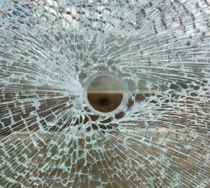
For example, 9⁄16-inch-thick laminated glass is comprised of (2) ¼-inch-thick tempered glass panels bonded together by a polymeric interlayer. Laminated glass panels have different structural behaviors than monolithic glass panels, particularly bearing stresses occurring on the edge of holes in the glass. Figure 7 shows a typical 9⁄16-inch-thick laminated glass panel for a point supported glass railing tested to failure. The glass breakage occurred at the left side of the standoff attachment hole, and, in this case, the compression side ¼-inch glass panel layer failed. It is consistent with the high stress concentrations shown near the hole edge in Figure 6. Not surprisingly, ½-inch monolithic glass panels resist the concentrated stresses much better, and the same testing process resulted in much higher test loads being applied before breakage.
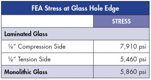
The Table shows an FEA stress comparison analysis for a point supported 9⁄16-inch-thick laminated glass and a ½-inch-thick monolithic glass with an identical layout and design load applied. The stress in a ¼-inch single ply in the laminated glass is significantly higher than the stress that the FEA model shows for the full ½-inch-thick panel. In summary, this data shows that laminated glass panels do not work as well as monolithic glass panels. The glass railing engineer should carefully analyze the hole edge stresses for point-supported glass railings without top caps.
For this example, there are generally two engineering solutions to accommodate laminated glass in standoff guards without a top cap: 1) use thicker laminated glass and/or 2) increase the number of standoff supports. Thicker laminated glass is much more costly to the building owner, and added standoffs change the look, which can be unappealing to the architect. Both options typically make the structural engineer the bearer of bad news.
Guidance for the Glass Railing Structural Engineer
Since base shoe style balustrade railings are more commonly used in sports arenas, theaters, and other public gathering areas common for live viewing events, designers could infer that the Code Council intended the top rail exception in the code to apply to base shoe glass balustrades only. It is questionable whether standoff style guardrails should be included in the top rail exception rule, as the Code Council does not define what exactly constitutes a structural baluster. Based on the engineering data above, the top rail exception rule inadvertently causes structural design issues in the glass for point-supported glass railings due to the laminated glass requirement. Regardless, whenever the architect exercises the right to use the top rail exception for point-supported glass railings, the delegated design engineer should exercise caution to ensure the laminated glass is thick enough to resolve the concentrated flexural and edge stresses at the standoff support holes.
To Top Rail or Not to Top Rail?
In the 2018 edition of the International Building Code, the Code Council has provided an answer to whether or not a glass guard can exclude the top rail. An updated version of the top rail exception rule has been included in IBC 2018, Chapter 24, Section 2407.1.2:
2407.1.2 Structural glass baluster support. Guards with structural glass baluster panels shall be installed with an attached top rail or handrail. The top rail or handrail shall be supported by not fewer than three glass baluster panels or shall be otherwise supported to remain in place should one baluster panel fail.
Exception: An attached top rail or handrail is not required where the glass baluster panels are laminated glass with two or more glass plies of equal thickness and of the same glass type. The panels shall be tested to remain in place as a barrier following impact or glass breakage in accordance with ASTM E2353.
The critical point with the re-worded exception is that it replaces the previous disclaimer “when approved by the building official” with a provision that all laminated panels used without top caps need to be tested per ASTM E2353: Standard Test Methods for Performance of Glazing in Permanent Railing Systems, Guards and Balustrades. The testing requirement applies to all glass baluster railing configurations, including base shoe and point-supported glass balustrades.
The updated exception in the 2018 IBC could affect architects and glass guardrail manufacturers that plan to continue using laminated glass panels without a top rail because the ASTM E2353 method is an extensive testing procedure that includes impact testing and post breakage requirements. However, this added testing requirement will help alleviate structural design concerns with laminated glass used in glass balustrades that do not have top rails.
Where Do We Go from Here?
Although the International Code Council can be commended for addressing the lack of oversight regarding the top rail exception rule, it is unclear how ASTM E2353 testing is supposed to be incorporated into the design process. From an engineering perspective, the ASTM E2353 testing qualification is similar to the safety glazing requirements already referenced in IBC Chapter 24, Section 2407.1. Historically, safety glazing qualification testing is the responsibility of the glass manufacturer. As the IBC 2018 and IBC 2021 become the governing codes for construction projects throughout the U.S., glass railing manufacturers are encouraged to communicate with their glass suppliers to be prepared for this latest update of the top rail exception rule for glass balustrades. Currently, twenty-five U.S. states have adopted the IBC 2018, while South Dakota, Colorado, and Wyoming have already adopted the IBC 2021, including the same top rail exception discussed in this article.■