
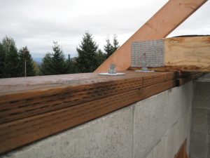
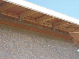
The phrase “the devil is in the details” applies to anchor bolt design in masonry structures. The anchorage of masonry members is essential both for load transfer into the member and for stability and support of the member. There are typically two types of anchors used in masonry. Cast-in-place anchors, or anchor bolts, are generally designed using TMS 402 Building Code Requirements for Masonry Structures. Post-installed anchors are generally designed based on manufacturers’ data, with the design capacities of the anchors determined through International Code Council (ICC) Evaluation Service reports. This article focuses on anchor bolt design and, particularly, several recent revisions in the 2016 version of TMS 402 that will help with the design of anchor bolts.

Brief History of Anchor Bolt Design
Before the 2008 TMS 402 code, there was a vast difference between strength design and allowable stress design in how the strength of an anchor bolt was determined. The provisions were harmonized in 2008, so that allowable stress design and strength design give reasonably the same design. There are now three failure modes considered for tension: steel yielding, masonry breakout, and anchor bolt pullout (bent-bar anchors only). Often, the anchor bolt pullout equation will control for bent-bar anchors; thus, headed anchors are often preferred for large-tension loads. Four failure modes are considered for shear: steel yielding, masonry breakout, masonry crushing, and anchor bolt pryout. Masonry breakout will only control if the anchor is near an edge. Anchor bolt pryout will only control for very small embedment lengths. Masonry crushing is usually the failure mode that controls the design capacity.
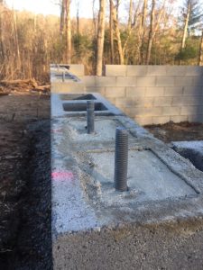
The masonry code has always required at least a ¼-inch clearance between the anchor bolt and masonry unit for fine grout and a ½-inch clearance between the anchor bolt and masonry unit for coarse grout. In the 2011 code edition, this provision was clarified for anchor bolts placed in drilled holes in the face shells of hollow masonry units. The anchor bolt is permitted to contact the masonry unit where the bolt passes through the face shell, but the portion of the bolt within the grouted cell still has to maintain the minimum space between the bolt and the unit.
Anchor Bolts Provisions in TMS 402-16
There were two major changes to anchor bolt provisions in the 2016 version of TMS 402. One change was to increase the shear capacity due to masonry crushing by 67 percent. The second change modified the interaction equation for combined tension and shear loading from a linear interaction to an elliptical interaction, increasing the calculated capacity of anchor bolts.
Designers have expressed concerns about the masonry crushing equation. The existing equation results in very closely spaced anchor bolts, to the point that designs seem unreasonably conservative. When the masonry crushing equation was added to the TMS 402 code in 2008, there was no comparison to test data. The nominal masonry crushing strength was 1050√f´mAb, where f´m is the specified masonry compressive strength and Ab is the bolt area.
Test data from 345 anchor bolt tests were recently examined. Shear crushing controlled in 188 of the tests. Shear crushing was not necessarily the actual failure mode but the equation that controlled the design capacity. The average ratio of the experimental strength to the nominal strength was determined to be 2.33. In other words, anchor bolts were failing at over twice the predicted nominal strength.
Several modifications to the current crushing strength were examined, and the equation recommended by FEMA 368 (2000 NEHRP, Recommended Provisions for Seismic Regulations for New Buildings and Other Structures) was chosen. This equation is 17504√f´mAb. A similar increase was made for allowable stress design. Re-examining the 345 tests showed that shear crushing was controlled in 131 of the tests. The average ratio of the experimental strength to the nominal strength was 1.49, or the anchor bolts were failing at approximately 1.5 times the predicted nominal strength.
The second change in anchor bolt provisions in TMS 402-16 was related to anchor bolts under combined tension and shear loading. The interaction equation for combined axial tension and shear in anchor bolts in masonry has historically been a linear interaction equation in the TMS 402 code. This is quite conservative. The TMS 402-16 code changed this to an elliptical interaction equation with an exponent of 5⁄3, as shown below. A similar change was also made to the allowable stress design interaction equation:

where bau is the strength level axial load on an anchor bolt, bvu is the strength level shear load on an anchor bolt, ban is the nominal axial strength of an anchor bolt, and bvn is the nominal shear strength of an anchor bolt.
The basis for this change was again the examination of test data of anchor bolts under combined tension and shear loading. The change is significant. For example, for a value of bau/φBan = 0.5, a linear interaction would limit bvu/φBvn to 0.5. With the new elliptical interaction, bvu/φBvn could be as high as 0.8 for bau/φBan = 0.5.
Changes to ASCE 7
In addition to the changes to the anchor bolt requirements in TMS 402, there was a change in anchor provisions in ASCE 7, Minimum Design Loads and Associated Criteria for Buildings and Other Structures. In ASCE 7-10, the seismic requirements in Chapter 13 (nonstructural components), Chapter 14 (material-specific requirements), and Chapter 15 (nonbuilding structures) required that the anchor loads be increased by a factor of 2.5 if the failure was controlled by other than tensile or shear yielding. This factor was reduced from 2.5 to 2.0 in Chapter 14 of ASCE 7-16. The increase in Chapters 13 and 15 is based on an overstrength factor that ranges from 1.5 to 2.5 but is 2.0 for almost all cases.
Conclusions
The two major changes in the anchor bolt provisions of TMS 402-16, increasing the shear crushing strength and changing from a linear to an elliptical interaction equation, will significantly affect anchor bolt design. The changes will result in more efficient designs and reduce the excessive conservatism in previous codes. Based on several trial designs, these two changes, combined with the change in the ASCE 7-16 seismic provisions, result in an approximate doubling of the calculated capacity of anchor bolts.■
We are excited to see a lessening of the pandemics’s impact on our authors and advertisers and expect to have more normal page counts in the future. As a result, we have taken the opportunity to showcase the work that other organizations do in supporting SEs by reinvigorating our Guest Column program. It is a pleasure to have these organizations add to STRUCTURE’s knowledge base. If your organization would like to submit an article proposal, please contact Chair@STRUCTUREmag.org.
This article, all or in part, has been previously published in the Masonry Design, May 2018 issue. It is reprinted with permission.