
Part 2: Significant Changes to Design and Detailing Requirements
Significant changes were made to the design and detailing requirements for special steel-reinforced concrete structural walls in the 2019 edition of Building Code Requirements for Structural Concrete (ACI 318-19) (hereafter referred to as ACI 318).
Part 1 of this article (STRUCTURE, April 2022) covered the following changes:
- The introduction of Grade 80 and Grade 100 deformed bars to resist the effects of flexure, axial force, a combination of axial force and flexure, and shear.
- New requirements for longitudinal bar termination and splice locations.
- New requirements for minimum area of boundary longitudinal reinforcement for slender walls.
Part 2 provides information on the following revisions:
- Increase of the design shear force for slender special structural walls.
- New requirements for expected wall deformation capacity and expected wall drift demand.
- Revised details for transverse reinforcement within boundary elements and the wall web.
- New maximum vertical spacing requirements of transverse reinforcement at wall boundaries.
Design Shear Force
Prior to the 2019 edition of ACI 318, shear strength requirements for special structural walls were based on the maximum factored shear force, Vu, obtained from analysis of the structure using the prescribed earthquake loads in ASCE/SEI 7 Minimum Design Loads and Associated Criteria for Buildings and Other Structures. These shear requirements are inconsistent with those for beams, columns, and joints in special moment frames, which are based on capacity design. Also, due to actual earthquake ground motion, shear forces can be considerably larger than those obtained using ASCE/SEI 7 loads. Thus, the shear design requirements for special structural walls in ACI 318 before 2019 do not ensure ductile flexural yielding occurs prior to shear failure at the critical section.
New shear design requirements were introduced in the 2019 edition of ACI 318 to address these issues. The design shear force, Ve, for special structural walls must be calculated by ACI 318 Eq. (18.10.3.1):
Ve = ΩvωvVu ≤ 3Vu
In this equation, Ωv is the overstrength factor, which is equal to the greater of Mpr/Mu and 1.5 for walls with a height-to-length ratio hwcs/lw > 1.5. The term hwcs is the height of the entire structural wall above the critical section. For walls with hwcs/lw ≤ 1.5, Ωv = 1.0. The minimum Ωv = 1.5 is based on Mpr = 1.25Mn = 1.25Mu/0.9 = 1.4Mu. A value of 1.5 was selected because the amount of longitudinal reinforcement provided in a structural wall, which has a direct impact on Mn, is typically greater than the required amount.
The probable flexural strength, Mpr, is determined using the properties of the wall at the critical section, assuming the stress in the longitudinal bars is equal to 1.25fy and the strength reduction factor, φ, is equal to 1.0. The factored bending moment at the critical section, Mu, is obtained from analysis of the structure using the ASCE/SEI 7 prescribed loads. Because Mpr and Mn depend on the factored axial force at the critical section, the condition producing the largest value of Ωv must be used to determine Ve.
The dynamic amplification factor, ωv, is determined by ACI 318 Eq. (18.10.3.1.3) for walls with hwcs/lw ≥ 2.0:
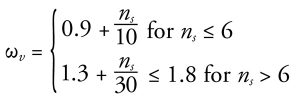
In this equation, ns is the number of stories above the critical section, which must not be taken less than 0.007hwcs (this limit is imposed on ns to account for buildings with large story heights). For walls with hwcs/lw < 2.0), ωv = 1.0.
The dynamic amplification factor accounts for the response of a multistory building with changing patterns of lateral inertial forces (mode shapes). Accounting for higher modes can shift the centroid of the lateral forces downward, thereby increasing the shear force at the critical section.
Where Ve is calculated by ACI 318 Eq. (18.10.3.1), it is permitted to take φ = 0.75 when determining the design shear strength, φVn, of a slender special structural wall. In addition to the overstrength and dynamic amplification factors, the redundancy factor, ρ, must be included in the determination of Ve where required by ASCE/SEI 7 Section 12.3.4.2.
It is evident that Ve can be significantly greater than Vu (up to a factor of 3 times), which will most likely require thicker walls and/or more transverse reinforcement. The SEAOC Seismology Committee’s SEAOC Blue Book: Seismic Design Recommendations has contained a similar method for determining Ve for many years.
Drift Capacity Check
New drift capacity requirements must be satisfied for slender special structural walls (hwcs/lw ≥ 2.0) where special boundary elements are required in accordance with ACI 318 Sect. 18.10.6.2. Either of the following drift capacity checks must be satisfied in such cases:
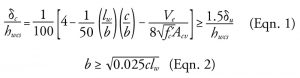
In these equations, δc = wall displacement capacity at the top of the wall; b = width of the compression face of the wall; c = largest neutral axis depth calculated for the factored axial force and bending moment consistent with the direction of the design displacement, δu, at the top of the wall; and Acv = gross area of the wall web minus the area of any openings.
The term δc/hwcs represents the drift capacity, which need not be taken less than 0.015, and (1.5δc/hwcs) represents the drift demand. Satisfying this drift capacity check results in a low probability of strength loss for the design earthquake. For walls without flanges, b is equal to the thickness of the wall. If b varies over c, like for walls with flanges, an average value of b should be used considering the effective flange width defined in ACI 318 Section 18.10.5.2.
The second equation is derived from the first equation, assuming Ve/8√f´c Acv = 1.0 and δc/hwcs = 0.015.
Detailing Requirements
Many new and revised detailing requirements have been introduced in the 2019 edition of ACI 318 for special structural walls. These requirements, found in ACI 318 Sections 18.10.6.4 and 18.10.6.5, are based primarily on observations from recent earthquakes and laboratory tests. The main revisions are:
- Transverse reinforcement spacing limits were revised in special boundary elements, including new maximum vertical spacing limits for Grade 80 and Grade 100 transverse reinforcement within and outside of the region of anticipated yielding.
- A new limit is placed on the length of a hoop leg relative to the thickness of the confined core within a special boundary element. Where this limit cannot be satisfied, adjacent overlapping hoops must be used with an overlap length of at least the lesser of 6 inches and two-thirds of the boundary element thickness.
- Web vertical reinforcement must have lateral support provided by the corner of a hoop or by a crosstie with seismic hooks at each end for a distance above and below the critical section of at least the greater of lw and Mu/4Vu (that is, within the region of anticipated yielding).
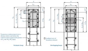
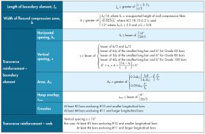
These revisions, along with the other detailing requirements for special structural walls, are illustrated in Figure 3. Hooked and headed transverse reinforcing bars can be utilized in any special structural wall and not just in the configurations indicated in the figure.
More in-depth information on the changes outlined in this article, including design aids and worked-out examples, can be found in the Concrete Reinforcing Steel Institute’s (CRSI) Design Guide on the ACI 318 Building Code Requirements for Structural Concrete. Also available is the CRSI Design Checklist for Special Steel Reinforced Concrete Structural Walls, which contains an easy-to-use list of essential items that must be completed when designing and detailing special structural walls. Visit www.crsi.org for more information on these and other CRSI resources.■
References
ACI (American Concrete Institute). 2019. Building Code Requirements for Structural Concrete and Commentary. ACI 318-19, Farmington Hills, Michigan.
American Society of Civil Engineers (ASCE). 2017. Minimum Design Loads and Associated Criteria for Buildings and Other Structures, ASCE/SEI 7-16, Reston, VA.
CRSI (Concrete Reinforcing Steel Institute). 2020. Design Guide on the ACI 318 Building Code Requirements for Structural Concrete. Schaumburg, IL.
CRSI (Concrete Reinforcing Steel Institute). 2022. Design Checklist for Special Steel Reinforced Concrete Structural Walls. Schaumburg, IL.
SEAOC Seismology Committee. 2019. “Reinforced Concrete Structures.” The SEAOC Blue Book: Seismic Design Recommendations, Structural Engineers Association of California, Sacramento, CA.