
Securing Historic Artwork through Structural Ingenuity
Pan American Unity is the largest contiguous mural created by Diego Rivera and his last work in the United States. Timothy Pflueger invited Rivera to paint the mural for the Golden Gate International Exposition, which took place on Treasure Island, San Francisco, in 1940. He participated in a special exhibit called Art in Action, where the spectators could experience the artistic process firsthand as muralists, painters, sculptors, and other artists performed their work live.
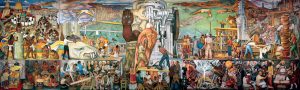
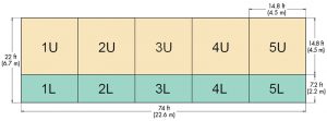
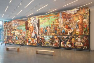
Pflueger and Rivera designed the mural to make Art in Action portable. Unlike the original fresco painting technique, where a building’s wall supports the multiple plaster layers, Pan American Unity is formed by ten panels with metal frames that hold and protect the fresco layers (Figure 1).
Twenty years after the fair ended, in 1961, Rivera’s masterpiece was installed in the City College of San Francisco’s (CCSF) Diego Rivera Theatre. Unfortunately, however, the building was seismically unsafe, and plans to relocate the mural were needed once more. Additional historical documentation can be found on the Diego Rivera Mural Project’s website (riveramural.org).
In 2017, San Francisco Museum of Modern Art (SFMOMA) announced the plans to move Rivera’s masterpiece to the Roberts Family Gallery for a temporary exhibition. The safe relocation of this cultural treasure was complex and challenging. Therefore, CCSF and SFMOMA assembled a team of international experts in conservation, engineering, science, and art handling to determine how to remove, transport, and reinstall the mural without damaging this priceless work of art. Holmes provided the structural engineering consulting through the design of the supporting structures. A team of experts from The National Autonomous University of Mexico (UNAM) was engaged to research the fresco’s materials and perform large-scale mock-ups to inform the preservation team of relocation methodologies. Atthowe Fine Arts, the art handler and fabricator, advised on removal, handling, and transportation logistics.
Mock-up and Testing
Although CCSF’s Diego Rivera Mural Project had done an outstanding job collecting the historical documentation about Pan American Unity, the technical details of the mural and original installation were largely unknown.
In June 2019, the UNAM and Holmes’ teams met to plan the removal and relocation. One of the activities involved core-drilling the outer wall of the theatre to uncover, for the first time in almost 60 years, what was behind the iconic arrangement of colors of the pictorial layer. The team took photographs and measured vibrations and the mural dimensions to document its composition and supporting structure.
With this information, the team built precise 3-D models and technical drawings that culminated in creating a full-scale replica of each type of panel. Those models were used to create simulations that allowed quick iterations between handling approaches. Furthermore, the mock-up panels aimed to understand their behavior in the presence of vibrations and impacts. They were also used as test specimens to validate the final de-installation approaches and detect cracks in brittle materials.
The experiments were carried out in the UNAM School of Engineering’s Center for Mechanical Design and Technological Innovation (CDMIT). These experiments included a logarithmic decay test to identify the dynamic parameters of the panels, the comparison of Nelson Stud cutting methods to select the tool that induced the least vibrations to the fresco, hoisting tests to validate the panel manipulation approaches, and resistance tests in which the panels were bent and hit to understand how cracks were made.
Structural Sequence
The structural design for the relocation and final housing of the murals required: 1) a new panel mount to support each mural panel, 2) a vibration-isolated travel cart and frame to protect the panel during transportation, and 3) a display structure to support the panel mounts in their temporary location at SFMOMA.
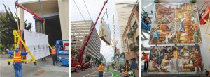
Each frame was designed and detailed with the intent of a seamless installation to each other. First, each de-installed existing mural panel frame was welded to the panel mount. The panel mount was then connected to the travel cart, which was rigged to the travel frame (described later). Finally, the assembly was picked entirely onto a truck bed. Upon arrival at SFMOMA, the travel cart was removed from the travel frame, rolled into the gallery, and lastly connected to the display structure. See Figure 2 for images of the structural sequence from beginning to end. Due to the integration of the frames, it was critical to evaluate the loading at each stage to ensure the controlling demands on the frames and connections were identified.
Panel Mount and Travel Frame
The panel mounts were framed out of HSS tube steel and internally braced by steel rods. Spaced around the perimeter of each frame were L-angle brackets that connected to the existing mural frame through welded studs.
The Nelson Stud welding technique was considered safe after analyzing its effects on UNAM’s mock-up panels. Heat flow was recorded using a thermographic camera, which allowed the researchers to understand the temperature gradients in the panel. The heat was contained to the surface of the beam that was in direct contact with the welded stud and a small portion of the beam’s web. Furthermore, it was found that the temperatures decreased quickly after the weld was complete.
The panel mounts were modeled using a linear analysis with support conditions at each stage represented by the connections to the travel frame or display structure. Finally, the model extracted the reactions to design the travel frame, display structure, and connections.
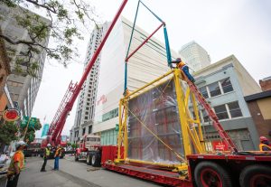
The travel frame, strapped onto the truck bed (Figure 3), navigated the hilly and uneven streets of San Francisco. Additional challenges that needed to be accounted for in protecting the mural during its transportation included overhead mass transit electrical lines, impacts to the panels, dangerous vibrations, and a large wind event.
To add further complication, the travel frame could extend no further than 15 feet 9 inches above the flatbed due to the truck’s requirements. Therefore, it was coordinated with the City of San Francisco to remove all overhead electrical lines along the truck’s path of travel. However, as an added layer of assurance, the top of the travel frame was built 1 inch above the top of the mural and inset with a steel ladder-like framing for a non-conductive structural cover to be laid over. Due to the maximum height limitation of the travel frame, the design of the travel cart involved very narrow tolerances. The 15-foot-tall existing mural was only 2⅞ inches above the truck bed.
The travel cart and frame were connected through wire rope isolators to mitigate vibration and motion induced by the truck during transportation. The first stage in designing the isolator’s parameters was a vibration test conducted by the UNAM, Atthowe, and SFMOMA teams. Next, the same trucks used for the mural were instrumented to log the accelerations that occurred while traveling on a representative road of San Francisco. Finally, the no-load and full-load scenarios in the trucks were tested. The results were the NLTH forcing functions which were used to tune the stiffness of the isolators and predict their performance during the move. The wire rope isolators effectively reduced the acceleration amplitudes by about 40% to 50% in the fresco compared to the truck’s base.
Upon arrival at SFMOMA, the travel cart was extracted from the frame, and 4-foot-long outriggers (4 total) were slotted into each end of the travel cart for stability. The purpose of the outriggers was an assurance against the event of a powerful gust of wind overturning the entire frame as it is rolled into SFMOMA.
Display Structure Design
The temporary display structure at SFMOMA was unable to be anchored through the gallery’s terrazzo floor tiles. Hence, the columns are braced back to the existing structure only through two horizontal truss diaphragms connecting to the building columns instead of anchoring into the slab below.
After the cart had been removed from the travel frame, it was rolled in front of the display structure. Lifting outriggers were integrated into the top of the display structure to hoist the panels into place (Figure 2).
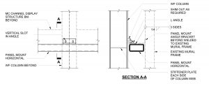
Attached to the display structure at the corresponding top corners of the panel mounts are steel seats for the panel mount HSS member to bear on as the frame is hoisted into place
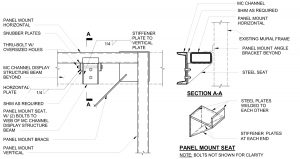
(Figure 4). The panel mount was able to slide horizontally on the seat so adjacent panels could run up against each other with minimal gaps in between. The bottom connection between the panel mount and display structure contained a 1-inch vertical slot to provide the vertical adjustability for the upper and lower panels to be flush (Figure 5). Careful attention was paid to the panel mount and display structure connections. Appropriate adjustability and tolerances were provided to allow the fresco panels to achieve a perfect alignment.
Conclusion
The Diego Rivera Pan American Unity Mural was successfully installed in SFMOMA’s Roberts Family Gallery on June 28th, 2021 (Figure 6).
After years of planning, meetings, site visits, testing, and design iterations, the engineering teams from UNAM and Holmes helped preserve and protect Rivera’s masterpiece for all to enjoy for generations to come.■