
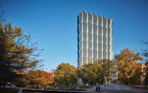
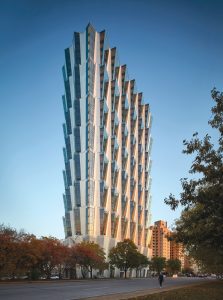
St. Louis’ latest high-rise building, the 36-story 100 Above The Park, brings a new flavor of architecture to the Gateway City (Figure 1). Eight tiers of stacked and undercut floor plans, each four stories high and shaped like the leaves of a tree, create a form at once organic yet modern. Magnusson Klemencic Associates (MKA) teamed with Studio Gang Architects (SGA) to make this unconventional form a reality by using novel framing solutions following this leaf-like building form. The result embraces Forest Park immediately to the west and provides a direct line-of-sight to the Gateway Arch to the east.
A Form Reflecting the Eye of the Beholder
100 Above the Park has been likened to a corona, icy shards of glass, or glowing canyon walls. These seemingly contradictory aesthetics all present themselves depending on the viewer’s location and the light in the sky. As imagined by the architect, the core vision for the building form was to create living spaces that were each unique, private, and generous with views. Typical floors have 11 apartments, each of which is a “corner” unit. The extended prow of primary living spaces creates the overall leaf shape of the floorplan.
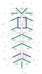
Rather than resist this form using a conventional layout of orthogonal columns and walls, the structure works with this geometry, following the concept of veins in a leaf. The primary arrangement of columns, slab reinforcement, and P.T. tendons is set at a 130-degree angle about the centerline of the building. This creates primary lines of support and load paths that follow the layout of units, leveraging the unique floor plan to stiffen key points around the slab’s perimeter. These locations, found at the narrow points around the slab edge, allow each glazed tip to be column-free while also maximizing slab cantilever distances. Following this same geometry, the south shear wall demises the 130-degree-oriented units and straightens briefly where east and west segments are coupled above the central corridor (Figure 2).
The unique geometry of the building also brought into question the validity of using ASCE 7, Minimum Design Loads and Associated Criteria for Buildings and Other Structures, prescriptive wind loads, which were developed using regular and prismatic archetypes. As a result, Rowan Williams Davies & Irwin Inc. (RWDI) was retained as the wind consultant for 100 Above the Park, conducting studies on primary building loads, cladding pressures, and “pedestrian” effects (i.e., the wind pressures and turbulence that would be felt regularly on the roof terraces).
Wind tunnel testing was conducted using a 1:300 scale model of the subject building and all buildings of significance within 1,200 feet. Such proximity modeling captures the effects of buffering or buffeting that may result from the turbulent airflow around upwind structures. In the case of 100 Above the Park, adjacent building effects were far less critical than the shape of the building itself.
It is common for wind tunnel testing to reveal cross-wind responses for tall towers. This is a phenomenon in which wind blowing in one direction causes rhythmic sway in the perpendicular direction. Cross-wind response can define the governing design loads and create accelerations that are unacceptable to building occupants. When such a response is revealed during testing, the many remedies typically discussed include reshaping the tower to create roughness along the façade to break the slipstream effect along the sides. 100 Above the Park was several steps ahead of this conversation. The leaf points in plan and the undercut terracing in elevation are precisely the perimeter irregularities that the wind consultant would have recommended for a problematic building. Although the wind tunnel revealed overall wind loads up to 10% greater than ASCE 7 prescriptive loads, cross-wind response was virtually non-existent, with dominant loading clearly parallel to the wind direction (drag loads).
Overhanging Façade – Sawtooth Columns
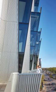
The architectural concept also incorporates extensive private roof terraces (Figure 3). Unlike typical apartment towers where balconies are stacked repetitively, each shading the one below, the terraces at 100 Above the Park are all open to the sky. This is a luxury typically provided only to penthouse units. Adding to the actual 14,500-square-foot roof are an additional 23,000 square feet of occupiable roof terraces created at the top of the four-story tiered stacks.
This form is created where three successive floors extend farther from the building centerline than the floor below. The fourth floor then returns to the original and smaller leaf shape, and the cycle is repeated. This setback at the top of each four-story stack becomes additional rooftop space around the entire perimeter of the building, yielding each unit approximately 175 square feet of private terrace.
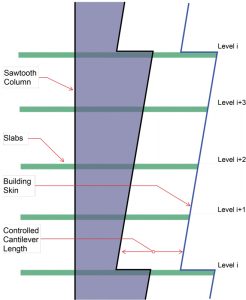
To accommodate the undercut tiers form, the support points around the building perimeter must extend outward along with the building façade. The relationship of column location to terrace cantilever tip is held consistent by the use of sawtooth concrete columns (Figure 4).
While three faces of the sawtooth columns remain vertical and create consistent demising locations within the apartments, the outer face slopes upward and outward on the same four-story slope as the building perimeter. The vertical sawtooth geometry is present in all 15 tower columns, allowing the tips of the leaf veins to stiffen and support the leaves as they grow and shrink.
Transferring Half a Tower
The relatively narrow project site, averaging 130 feet from east to west, necessitates parking and vehicle circulation to reside partially under the tower. A ground floor filled with retail, lobby, and back-of-house space is topped by five stories of modest-slope, on-ramp parking for 250 vehicles. Parking is most efficient when laid out in an orthogonal pattern. A framing grid of 28- by 60-feet allows three stalls to be arranged off each side of a central drive aisle. However, the leaf-and-vein layout of 32 levels of residential framing above certainly does not conform to this parking ideal.
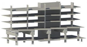
Zoning constraints limited the wider podium of the building to no higher than six stories. This meant that optimum parking efficiency needed to be established to satisfy the project parking requirements. The structural solution was for every tower column on the eastern side of the building to be transferred over the podium drive aisle (Figure 5).
Seven concrete transfer beams carry seven tower columns, the largest of which is five feet wide and seven feet deep on spans up to 34 feet. This web of beams delivers the tower column vertical forces, as large as 4,900 kips ultimate, to nine podium columns, the central core, and the south shear wall. The resulting space below is free and clear for optimized parking.
Quality Rock… But Where?
The project site is underlain by karstic limestone, which has the characteristic of being highly variable in geometry, including abrupt elevation changes and the potential for voids. The project geotechnical engineer, Geotechnology Inc., based recommendations on auger borings that reached refusal at a depth varying between 55 and 73 feet below ground surface. Rock samples indicated Rock Quality Density (RQD) values as high as 97% for high-quality limestone, generally known as soft rock.
Due to the uncertainty of the bedrock profile across the full site, as well as the common occurrence of a weathered lower-capacity top layer, preliminary recommendations called for the entire building to be supported on drilled piers with tip elevations between 65 and 76 feet below ground surface. These recommendations intended to have the best estimate of the actual subgrade conditions, with verification to occur before placement of any deep foundation elements. At each of the 57 drilled piers, probe holes were drilled as near as possible to the centerline of the pier locations, extending two pier diameters below the tip elevation to verify the absence of voids. Testing the material extracted during this probe program verified that end-bearing values of 80 ksf and side friction values of approximately five ksf could be reliably used.
The final foundation design could not be completed until the probe and testing program was performed. In most instances, the preliminary recommendations adequately covered the variability of the limestone. However, in select cases, nine-foot-diameter concrete piers needed to be socketed as far as 15 feet into the limestone to achieve the intended capacity.
Summary
100 Above the Park embodies exterior geometries and interior residential spaces that have never before been created. The concrete frame, hidden within and below this new gem for the city of St. Louis, challenges how a residential building can be shaped, designed, and built. Without straying from the standard palette of structural elements of a high-rise concrete building – flat slabs, shear walls, (partially) rectangular columns, and drilled piers – 100 Above the Park delivers on its goal of immersing its residents in the canopy of Forest Park while creating an iconic westward expansion of the St. Louis skyline.■
Project Team
Owner: Mac Properties (Chicago)
SER: Magnusson Klemencic Associates (Seattle/Chicago)
Architect: Studio Gang Architects (Chicago)
General Contractor: Clayco (St. Louis)