
Converting an Introvert into an Extrovert
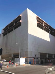
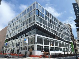
In 2016, Macy’s announced they were shuttering their Men’s Store in San Francisco’s Union Square, and Southern California-based developer Blatteis and Schnur partnered with Morgan Stanley with the intent of winning the development rights. Gensler signed on as the architect for the pursuit and, hopefully, the project, and the KPFF San Francisco office joined the team as both the civil and structural engineers. Although the structural work was initially viewed as renovation and a seismic retrofit, it soon became apparent that the intent would be a complete transformation. The Blatteis and Schnur/Morgan Stanley team submitted the winning bid, Plant Construction joined the team, and the adventure began.
Building Description
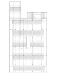
Originally designed in 1973 by Seattle engineers Hadley Properties, the single-tenant retail building has a floor plate of 31,000 square feet on each of eight levels, plus a one-story basement. The typical floor system shown in Figure 1 consists of 4½-inch-thick reinforced concrete slabs spanning east-west between 18-inch-deep post-tension pan joists. The pan joists span between 24-inch-wide by 18-inch-deep post-tensioned girders spaced at 32 feet on-center, and 7-foot-wide, 4½-inch-thick closure pour slabs were placed on the north and south sides to allow the pan joists to be stressed. 24-inch-square reinforced concrete columns supported the girders. The joists were turned approximately 30 degrees from square at the roof, effectively increasing the center-to-center span to 34 feet. The street-level slab was stepped in one location due to the sloping streets on the west and south sides. Reinforcement for the framing elements was typical for that era: 60 ksi yield strength, but light on shear reinforcement and confinement steel. Column foundations were spread footings, and wall foundations were grade beams with piers.
The lateral system consisted of perimeter reinforced concrete shear walls. On the north and east sides, the 12-inch-thick concrete walls had no openings to speak of and served as the fire separation walls for the adjacent properties. The building was held off the property lines on the north and east sides by 4 inches. Figure 2 shows the west and south elevations of the original structure. Adjacent to the storefront windows at the street level, the 22-foot-long west walls were 3 feet thick from the basement to the underside of the fourth floor and 12 inches thick above the fourth floor. Above the street-level storefront windows, the exterior elevation was solid 12-inch-thick reinforced concrete walls at the second through fifth floors. Similar to the west elevation, the south elevation consists of 30-foot-long, 2-foot-thick walls adjacent to the storefront windows, from the basement to the underside of the fourth floor, and 12 inches thick for the remaining levels.
Conceptual Design
The original building was designed for a single retail tenant when solid walls were acceptable, and natural light was sometimes an afterthought. The development team’s vision was to convert the lower three floors plus basement to retail (potentially multiple tenants at each level), two floors of space that could be office or retail (flex space), three upper floors of office space, and a rooftop restaurant. The team knew that the solid walls had to go, with corner spaces being a premium. The exact concept was yet to be determined, but Gensler recognized that the structural system would play a significant role in the vision, and KPFF’s team was brought into the conceptual design.
KPFF assembled a team of four engineers, a project manager, and a principal in charge and began analyzing the existing structure to assess the expected performance relative to a new structure. The existing lateral system turned out to be quite stiff, and the 4-inch seismic joint was adequate even by modern code standards. The gravity system was also generally adequate for the new intended use, except for the rooftop joists and girders, which appeared to be designed for 20 psf roof live loads. KPFF also evaluated the typical floor joists and found that the post-tensioning could be removed and still achieve the required capacity by adding reinforcing plates and carbon fiber wrap. Knowing the joists could be modified opened the architectural possibilities.
For the lateral system, one thing was clear: the west and south walls were going to be demolished. Gensler described this as “changing an introverted building into an extrovert.” The KPFF team rapidly assessed over forty possible schemes, including interior cores and exoskeletons of various configurations. Rapid lateral analyses were performed to verify the feasibility of each scheme to meet the current California Building Code (CBC), tuned it as required, prepared graphics files that Gensler imported into their SketchUp model, and prepared weekly presentations to the development team to accept or reject the proposed lateral bracing concept.
In the end, the ownership group decided that some form of core system would best suit their needs and allow for the most significant future flexibility. As the conceptual design progressed, they also expressed a desire for at least six feet of column-free space on the two street sides to allow flexibility in window displays and provide a terrace at the third floor. Structurally speaking, the request for column-free perimeter space was a relatively simple concept on the south edge due to the closure pour. However, removing columns on the west face meant modifying the existing post-tensioned girder, which would increase the cost significantly. Finally, ownership wanted the ability to demise the west side of the building into either three or four tenants to allow for the maximum future leasing options. This request meant columns would be moving.
KPFF is often asked if it would be simpler to demolish the building and design a steel structure that satisfies every request and allows maximum future flexibility. KPFF asked this question of the architectural and ownership teams every week until they were told to stop asking. The building is in a historic district in one of the busiest areas of San Francisco, and it was estimated that the Environmental Impact Review would take up to four years to compete, which put construction permits about five years into the future.
Selected Scheme
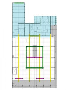
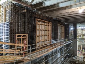
Figure 3 is an upper-level floor plan illustrating the selected scheme. The existing post-tensioned girders are highlighted yellow and originally extended from the west face of the building to a grid line 32 feet into the blue highlighted area. The magenta highlights are new 3-foot-deep concrete transfer girders at every floor. The blue highlighted region is a zone where the existing concrete floor system was replaced with steel framing to accommodate new elevator banks, exit stairs, and mechanical shafts. The existing floor framing was removed and replaced with cast-in-place concrete slabs in the gray highlighted zones for architectural reasons.
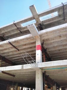
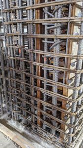
Shortening the girders and removing columns involved shoring the entire building at every level, as was described in the article by Robert Graff of Degenkolb in his recent article (STRUCTURE, January 2022). Once shored, the ends were cut to release the cables, and the concrete was removed to the face of the nearest support, either an existing column or new transfer girder. Next, the cables were retained, reprofiled, and the girder ends were repoured as cantilevers, as shown in Figure 4. The bottom girder end in Figure 4 shows the retained cables and longitudinal reinforcing, the middle girder has been poured and stressed, and the top girder has been poured and stressed while the column has been removed and the slab prepared for the transfer girder.
In addition to the work described for the typical floors and shown in Figure 3, two levels were removed entirely and replaced with steel framing: the ground floor and the roof. Due to the sloping streets adjacent to the building and the desire to allow for multiple retail tenants, the original ground floor framing was removed and replaced with steel framing stepped as established by Gensler. The roof was similarly replaced with steel framing because the original framing could not accommodate the dead and live loads of a restaurant and accessible outdoor landscaped space.
An outdoor terrace at the third floor wraps the building on the west and south sides, and its sloping soffit provides a dramatic focal point from the street level. The structural design included a horizontal steel truss cantilevering off the newly poured columns. The façade is clad with white terra cotta tiles to match the surrounding buildings, and KPFF’s Portland office was the structural engineer for the curtain wall.
The selected lateral scheme is highlighted green in Figure 3 and is designed to substantially meet the provisions and performance objectives of the 2016 CBC. The heavily reinforced core (Figure 5) covers two bays in each direction and is perforated with large openings to allow open retail spaces. Two additional lines of north-south bracing were required both for loads and for reducing torsion. From the basement to the underside of the fourth floor, the lateral system is special reinforced concrete shear walls which vary in thickness from 3 feet 6 inches at the west edge of the core to 2 feet elsewhere. From the fourth floor to the roof, the lateral system changes to buckling-restrained braces (BRB’s) to allow for clear views on the office floors.
The transitions from steel bracing to concrete cores were particularly challenging to detail and build. Steel beams were buried in the concrete beams, allowing for load transfer between the two materials and providing locations for attaching gusset plates (Figure 6).
Uplift on the frame columns was too high to rely on anchor bolts, so full-height steel columns were buried in the shear wall boundaries from the third to fourth floors. The confinement reinforcing maintained continuity by passing through predrilled holes in the buried columns.
The remaining significant revisions to the lateral system included widening the seismic joint and adding collectors and ties. The new lateral system was more flexible than the 1973 design, notably at the braced frame levels, so KPFF called for the installation of perimeter beams and columns on the north and east sides, removing the original 12-inch-thick perimeter concrete bearing walls, and cutting the floor slab back. Existing gravity columns were wrapped with carbon fiber to ensure ductile behavior when the building deflects during a major earthquake. Carbon fiber collectors resolved the diaphragm discontinuity issues created when merging new and existing concrete slabs.
Above the roof, the restaurant lateral system transitions to steel special moment resisting frames, while the back-of-house spaces utilize SureBoard sheathing as bracing. The KPFF San Francisco office currently provides structural engineering services for the new restaurant slated to open in 2022.
A project as complicated as 100 Stockton Street has a list of unknown conditions and lessons learned too numerous to mention in an article. However, the key to the entire project was that the structural team adopted a solutions-based mindset and abandoned the “problem-finding” mentality structural engineers can sometimes exhibit. Creating a rapid response team during conceptual design encouraged creative solutions. It ensured that the path taken throughout the design delivered a renovation and retrofit consistent with the development team’s expectations.■