
Part 2: Preserving Historic Value, Providing Modern Seismic Safety
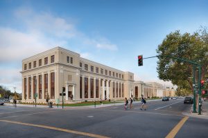
A California public school campus constructed in 1924, partially retro fitted in 1936, recognized as a historic place in 1977, vacated shortly after that in 1978, partially retrofitted again in 1989, shuttered in 2012, was brought back to life in 2018. For a brief history of the Historic Alameda High School campus and the state government regulations setting seismic safety standards for public school buildings in California, see Part 1 of this article series in the January 2022 issue of STRUCTURE.

The 1920s neoclassical-style buildings with ornate design elements copied from ancient Rome are truly beautiful and benefit the community of Alameda. However, it is not of great surprise that such historic concrete buildings were not designed and detailed with seismic performance in mind. Maintaining the regal aesthetics while upgrading to current code structural performance requirements proved challenging. Structural challenges included soil liquefaction; lightly reinforced, nonductile concrete walls; the absence of collectors; and inadequate out-of-plane concrete wall anchorage load paths. Any one of these deficiencies could lead to significant damage or possible collapse during a seismic event.
Analysis Options
Selecting a retrofit scheme starts with evaluating options for code-compliant analysis. The least onerous analysis approach is a voluntary retrofit using Sections 317.11 and 319.12 of the California Existing Building Code (CBC) (based on the International Existing Building Code). This option provides the Structural Engineer flexibility to choose which elements warrant retrofit and offer the best improvement for a given budget. However, a potentially overlooked requirement of this option is that a more dangerous condition must not be created as a result. For example, adding a shear wall is typically a significant improvement for most buildings. Still, the resulting change to the collector demand could lead to overstressing a gravity beam that also serves as a collector.
Another approach, since the Alameda High School buildings are historic, could be the California Historic Building Code (CHBC). This code is intended to allow the structural engineer to improve seismic safety while not compromising architectural heritage. Reductions in seismic demands are permissible to reduce the impact on the aesthetics and recognize the shorter remaining useful life for older buildings. Seismic design force reductions are on the order of 25% to 50%, and redundancy and overstrength factors used in the design of new buildings can also be ignored. The CHBC permits the structural engineer to exercise judgment in deciding which elements should be upgraded to improve seismic performance. However, this option is not permitted for California public school projects, as the seismic performance needs to be equivalent to the current building code for new structures.
This project was largely made possible by partial financial reimbursement from the State through the Seismic Mitigation Program (SMP; see Part 1 of this article series). To qualify for SMP funding, analysis options are limited to a full retrofit at current building code seismic levels in accordance with ASCE 41 Seismic Evaluation and Retrofit of Existing Structures or ASCE 7 Minimum Design Loads and Associated Criteria for Buildings and Other Structures. This involves analyzing all the building components of the seismic force-resisting system and retrofitting them as required to conform with one of these two current codes. Typically, ASCE 7 is more difficult to employ because it is often impossible to comply with the prescriptive detailing requirements and choose a code-defined lateral system. Therefore, ASCE 41 is often used with existing buildings that do not comply with current code prescriptive seismic detailing requirements since the document was written primarily for existing buildings. However, an ASCE 7 analysis is typically simpler compared to ASCE 41. In the end, ASCE 7 was chosen for this project because the existing components of the lateral system were too deficient to be of use (or absent entirely), and a full new lateral system was required.
Ground Improvement
In addition to structural issues above grade, the soil under the building posed a seismic hazard. The uppermost ten feet of soil was loose, granular, and located below the near-surface water table, creating favorable conditions for liquefaction to occur. Liquefaction is the sudden loss of soil strength during an earthquake resulting from pore water pressure increase; seismic waves turn the soil particles and surrounding water into a liquid solution, so foundation support is significantly reduced or lost. A mat slab or deep pier and grade beam foundation are good candidates for new construction at a liquefaction site; however, these are not feasible for large existing buildings.
Instead of designing a foundation to accommodate liquefaction, the soil properties were improved using compaction grouting. This process densifies loose sandy soil by injecting high-pressure low-viscosity cement grout columns below grade on a regular grid. The pressure-injected grout displaces and compacts the adjacent soil. Grouting was performed under and around footings in a triangular grid spaced at three feet on-center in each direction to a depth of ten feet and over a width extending five feet beyond the footprint of all footings. Careful monitoring was required to avoid ground heave, which would inadvertently lift the footings and damage the buildings. This ground improvement technique is expected to make the soil supporting the footings perform as if there were no liquefaction potential at all.
Braced Frames
By default, the existing seismic force-resisting system (SFRS) was concrete shear walls. The walls did not appear to be designed and detailed for in-plane seismic forces and, of course, lacked prescriptive detailing requirements. Retrofitting the walls by adding more rebar and more concrete was a non-starter since window openings would need to be infilled, affecting the historic architecture.
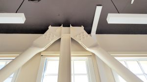
A new steel SFRS was another option to evaluate. Steel offers an efficient, compact, and modular solution. Relatively lightweight elements can be fabricated offsite then installed through small openings in the building. Comparing braced frames and moment frames, braced frames were selected due to their greater stiffness, which was required to limit in-plane drift of the existing concrete walls. Drift was limited to prevent yielding of the existing reinforcing steel in the concrete walls supporting floor and roof gravity loads. Braced frames also integrate better with wood-framed floors since the beam bracing requirements for moment frames are difficult to resolve into wood framing. Architecturally, it was decided not to encase the frames in finishes, so Cast Connex High-Strength Connectors were utilized at brace to gusset plate connections instead of traditional welded or bolted connections. The connectors are more visually appealing and allow for field bolted connections, which was more cost-effective to install.
Helical Piles
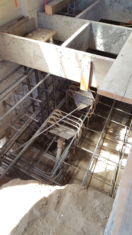
Three-story-tall braced frames supporting concrete wall construction result in sizeable seismic overturning demands. High demands combined with the need to fit new foundations within the footprint of an existing building, with pad footings throughout, required deep foundations. Due to limited access and vertical clearances within the existing building, helical piles were chosen for the new foundations that were installed under the braced frames. Helical piles are modular elements composed of relatively slender steel shafts with larger diameter helical plates on the lead end; essentially, a large screw torqued into the soil. These piles come in short lengths and can be installed with a hydraulic head mounted on a Bobcat, perfect for working inside an existing building. After one shaft is driven flush with the ground or slab, another shaft is added using a bolted coupler. Helical piles are stiff along their axis but weak perpendicular to the shaft. Therefore, vertical piles were used to support vertical forces but, to resolve base shear at the braced frames, battered piles at an angle of thirty degrees to vertical were used.
The pile manufacturer was unsure if the piles could be driven through the grout injection columns without damage and/or refusal. Therefore, the piles were installed first. After grout injection was performed, the foundations were excavated, taking care not to damage the embedded pile shafts. This was an unusual sequence but turned out to be successful.
Collectors
Existing concrete beam reinforcing was already fully utilized for gravity loads, so new collectors had to be introduced. It was challenging to integrate the new collectors with the existing gravity framing because they needed to occupy the same space to hide them from view and maintain historic visuals as much as possible. Braced HSS beams offered a small profile, which was hidden in the top of notched floor joist ends. Roof collectors were hidden in the attic. This resulted in only braced-frame elements being exposed in a limited number of rooms.
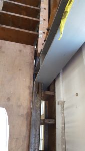
New steel collectors had to pass through perpendicular concrete beams in many locations. An elaborate set of condition-specific details was developed, using steel rods to limit the extent of concrete removal. Field welding was avoided in most cases, favoring a threaded rod and nut solution.
Diaphragms and Wall Anchorage
Upgrades to floor and roof diaphragms were required for both in-plane structure shears and out-of-plane wall forces. In-plane structure shears were quite high due to the heavy concrete walls and the desire to maximize the spacing of braced frames to limit the quantity and cost of new material. Wood structural sheathing panels were added on top of the existing diagonally or straight sheathed diaphragm to provide strength and ductility. The existing nominal one-inch-thick sheathing was utilized as blocking for the new panels; however, in a few locations, the existing sheathing had to be removed entirely to allow for the installation of a new high-load wood diaphragm.
A common deficiency of buildings with heavy walls and flexible diaphragms is out-of-plane wall anchorage strength, and these buildings were no exception. Light diaphragms brace heavy walls, and the result is typically catastrophic in a large seismic event. Insufficient wall anchorage can lead to loss of gravity support of floor/roof framing, as documented in the 1971 San Fernando and 1994 Northridge earthquakes. Horizontal hold-downs were added at approximately five feet on-center throughout the buildings to resist out-of-plane forces. Out-of-plane anchorage forces must be developed into the diaphragm, typically via attachment to perpendicular joist framing. Where the hold-downs did not attach to existing joists, blocking and light gauge steel straps were added to connect to a sub-diaphragm.
Success
Through the efforts of all stakeholders, the regal beauty of the Historic Alameda High School was preserved and has been extended to serve a new generation of students. Through careful coordination with the architect, neither aesthetics nor structural performance was sacrificed to reinvigorate the nearly century-old campus that sits just a few miles from the Hayward fault. Some (engineers) might even say it looks better now with the subtly exposed braced frames peeking through the historic framework.■