
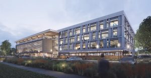
1951 Harbor Bay Parkway, a new building (Figure 1) located in Alameda, CA, was developed privately for use as commercial office space by a life-sciences company. The project provided the opportunity to utilize an innovative approach for seismic bracing that provides improved performance and cost-effectiveness over conventional braced-frame systems. The system uses concentric buckling-restrained braces (BRBs) in conjunction with a vertical mast or strong-back to reduce drift, eliminate weak stories, and increase redundancy. The yielding BRBs work in tandem with an elastic mast frame to create controlled rocking behavior that provides more resiliency and improved protection for the building frame, cladding, and interior construction.
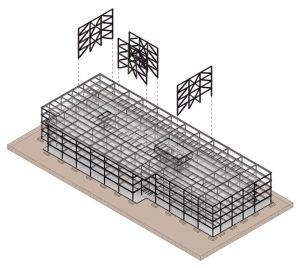
The four-story structure measures 384 by 141 feet in plan and provides approximately 220,000 square feet of total floor area. The ground story measures 16 feet tall, while the remaining stories are 14½ feet tall. A central core area provides accommodation for vertical circulation, restrooms, and utility spaces, allowing for flexible programming for the office areas. The regular column grid, measuring 32 by 25 feet, was laid out around the central core area to provide efficient span arrangements and floor assemblies. Floor framing consists of wide-flange beams supporting concrete slab on metal decking. Figure 2 depicts the structural layout and highlights the lateral support system.
System Overview
Special concentric braced frames (SCBFs) are typically among the most efficient solutions for resisting lateral loads for midrise steel structures in highly seismic areas. Incorporating BRBs is an effective way to improve the performance and reliability of these systems. The ductility and controlled response of the BRBs allows the structure to be designed for reduced seismic loads, making them a cost-effective alternative to conventional braces. In typical applications, braces would be arranged in a stacked chevron configuration to provide flexibility for locating window and door openings. The braces would also be located at numerous locations in each frame line at each story to provide redundancy in the system.
There are, however, shortcomings to this approach for both performance and economy. Under high seismic loads, these systems can experience large drifts that are concentrated at certain floors. This characteristic weak-story response increases the likelihood of localized damage needing repair and limits the ability of the building to function following a large earthquake. Ultimately, the full benefit of the BRBs is not effectively utilized since the ductility of the frame is limited by just a few critically loaded members.
Critical building elements, such as the structural frame, exterior cladding, interior construction, and elevators, are susceptible to damage resulting from concentrated story drift, which can hamper functional recovery following an earthquake. Improving resilience is about limiting the overall drift of the system and distributing that movement uniformly over the height of the structure. For SCBFs, this means counteracting the tendency for weak-story response and limiting the concentration of damage.
The key is to design the frame for rocking, rather than racking, under inelastic response. The rocking mechanism is achieved by introducing a stiff elastic spine into the frame capable of distributing forces between stories to create a more uniform drift profile.
The spine, sometimes referred to as a mast or strong-back, is essentially a vertical truss extending up the structure’s height and interconnecting the BRBs to form an integral framework. The vertical truss forming the mast is made of conventional steel members and is designed to pivot or rock at its base. The mast frame occupies the same footprint as a conventional frame but uses far fewer BRB members. The mast effectively forces all of the BRBs in the system to work together to resist movement at any story, which fully mobilizes the BRB elements’ deformation capacity and increases the system’s inherent redundancy.
Case Study
At 1951 Harbor Bay Parkway, several lateral-load resisting systems were evaluated for cost and performance. Moment-resisting frames provided maximum flexibility for space planning but were more costly and offered less seismic protection than braced-frame alternatives. Conventional SCBFs designed and proportioned according to ASCE 7, Minimum Design Loads and Associated Criteria for Buildings and Other Structures, and NIST guidelines were considered. Still, they were discarded in favor of an SCBF system using BRBs, along with a mast frame. The mast frame system offered an innovative approach to provide improved performance without additional cost.
The lateral frames comprised three bays of varying width, with the central bay being utilized as the mast frame when applicable. The outer bays varied between 23 and 26 feet wide, while the corresponding mast bays varied between 18 and 25 feet wide. Ultimately, the mast frame was comprised of 650 kip BRBs, W14x233 mast frame braces, and W14X283 columns.
Preliminary member sizing of the mast frame during schematic design was based on the assumption that the BRBs would resist the entire design lateral force, and the mast would be sized relative to the BRBs and their yield strengths. The vertical trusses that form the masts were designed to remain elastic and were proportioned using overstrength factors, similar to the design approach for columns. This design approach resulted in a costly and unnecessarily stiff structure. During initial analyses, the mast’s stiffness was identified as the primary influence on the structural response, so softening measures that allowed the structure to drift more were further investigated. The mast stiffness was predominately controlled by the footprint of the central bay relative to the outer bays of the lateral frames. As such, the stiffness was tied to the architectural programming to some degree, and softening had to be achieved without changing the column layout.
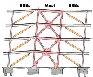
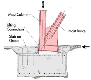
The mast frame’s rocking behavior (Figure 3) was key to the lateral system’s expected response, as it engaged the BRBs and provided the desired mode shaping. The mast frame base connections to the foundation elements are detailed to facilitate this rocking by permitting the base of the columns to uplift within a recessed pocket in the spread footing (Figure 4). As noted, the BRBs were initially sized to resist the entire design lateral force. Eventually, the mast braces were explicitly assumed to resist a portion of the design lateral force, allowing an approximate 30% reduction to the typical BRB yield strength. Even with the rocking mast in place, the mast frame still carried upwards of 65% of the design lateral force. As the yielding elements in the system, the BRBs still defined the seismic design criteria.
The final mast frame design was established through iterative equivalent lateral force (ELF) analyses with the member demands scaled by the appropriate overstrength factor, when applicable. The design was further validated through non-linear studies.
Results
The performance of the system scheme was evaluated using different analytical approaches. In addition to the standard equivalent lateral force (ELF) and response spectrum analysis (RSA) methods, non-linear static analyses and dynamic shaking simulations were used to gauge performance and validate design assumptions. Cost estimates were made by tracking steel tonnage and BRB quantities.
The suite of results studied indicated that the mast frame produces lower maximum story drifts and displacements than a conventional SCBF by up to 50%. Perhaps most importantly, the mast frame provided an essentially uniform drift profile without any major drift concentrations that might be typically observed in a more conventional frame. The dynamic analyses of the system showed that the mast frame was far less sensitive to variation in ground motions, with coefficients of variation at approximately 50% of that of conventional SCBF across results of interest for the suite of ground motions considered. In addition, the mast frame results showed improved utilization of the adjacent BRBs, while also providing more control of the BRB strain. Further studies of the redundancy of the frames were undertaken, where BRBs were removed from the analyses, and the mast frame results continued to display the previously listed advantages. In most cases, the advantages displayed were amplified when investigating the redundancy, with the mast performing as intended and redistributing lateral forces throughout the system.
These results were consistent with a previous case study, published in a March 2017 STRUCTURE article authored by Leo Panian, S.E., for a similar BRB mast system used in a four-story commercial building in nearby Berkeley, CA.
Key Takeaways
For the 1951 Harbor Bay Parkway project, the mast frame system required additional steel tonnage to achieve the design intent. The added cost was offset mainly by the overall reduction in the quantity of BRBs. The mast braces, beams, and columns were the main driver of the additional tonnage, as they had to be designed to transmit the forces that resulted from the yielding BRBs. The total tonnage of steel framing for the entire structure was approximately 12 psf, further validating the choice in lateral system as an economical one.
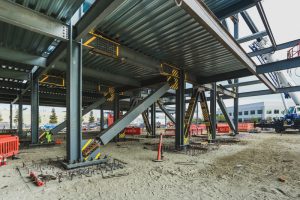
Constructability was a concern throughout the design process for a variety of reasons. The heavy steel elements and the atypical system were primary causes of concern. Still, collaboration with trade partners regarding the erection sequence and the use of typical gusset plates helped alleviate these issues (Figure 5). In addition, the heavy steel element connections were designed and detailed with small construction tolerances that could have been preemptively adjusted to allow more flexibility throughout the erection process.
While other jurisdictions may vary, the approval process for this lateral system was relatively seamless and did not require peer review, despite stepping outside conventional BRB frame design methods. Through more industry and academic research, prescriptive approaches may be developed to facilitate the approval process further and make the future implementation of similar systems more commonplace.■
Project Team
Structural Engineer: Tipping Structural Engineers, Berkeley, CA
Architect: brick., Oakland, CA
General Contractor: Pankow Builders, Oakland, CA
References
Astudillo, B., Panian, L., Simpson, B. Design and Performance Comparison of Strongback Systems and Typical Chevron BRB Frames. Proceedings of the 12th National Conference in Earthquake Engineering, Earthquake Engineering Research Institute, Salt Lake City, UT. 2022.
Simpson, B. and Mahin, S. “Experimental and Numerical Investigation of a Strongback Braced Framed System to Mitigate Weak Story Behavior.” Journal of Structural Engineering (ASCE) 2018; 144(2).
Simpson, B. and Torres, D. R. “Simplified Modal Pushover Analysis to Estimate First and Higher-Mode Force Demands for the Design of Strongback-Braced Frames.” Journal of Structural Engineering (ASCE) 2021; 147(12)
Panian, L. BRB Mast-Frames – An Improved Approach for Seismic Bracing (STRUCTURE, March 2017).