
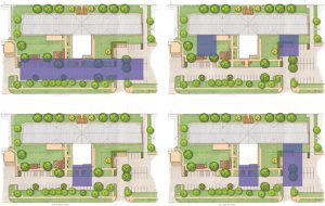
This Bachelor Enlisted Quarters (BEQ) project is a $60 million multi-story housing complex for enlisted military personnel. In addition to sleeping rooms, the facility includes an entry vestibule, quarterdeck, multi-purpose rooms, classrooms, laundry areas, and other support spaces. The T-shaped building results from multiple studies that considered site orientation and access, parking layout, view planes for future expansion, and more (Figure 1).
The project was a competitive design-build procurement based on a Request For Proposal (RFP). The general contractor, design-build subcontractors, and A-E Team were involved in intensive pre-design sessions to explore various design solutions and associated costs. Pricing documents with sufficient detail to budget the project were developed as a basis for the final bid.
Building Description
The building measures 380 feet in the north-south direction with an 80-foot extension in the east-west direction. The six-story building is 71 feet tall with an exterior consisting of face brick with reinforced concrete masonry backing and a hipped standing seam roof supported on cold-formed steel trusses bearing on the concrete roof slab (Figure 2).

Level 1 consists of a spacious centrally located quarterdeck, multi-purpose rooms, and other administrative spaces.
A total of 308 dormitory units are distributed along double-loaded corridors, maximizing daylight and views from the living quarters. Each unit has operable windows, which are punched openings in the exterior wall. Vertical circulation is provided through two centrally located passenger elevators, a freight elevator, and exit stairs located at the ends of the corridors.
The design is in accordance with the 2015 International Building Code (IBC) and other applicable Department of Defense (DoD) Unified Facilities Criteria (UFC). This Risk Category II building is designed for a wind speed of 115 mph and a seismic design category B.
Primary Structural Systems
Three different structural systems were evaluated: steel framing with composite deck, precast concrete with hollow-core planks, and a cast-in-place concrete structure. The steel solution increased building floor-to-floor heights, added fireproofing requirements, increased MEP distribution costs, and introduced uncertainties in steel costs due to new tariffs. In addition, the precast system proved difficult to meet the progressive collapse requirements. The cast-in-place system was selected because it provided the greatest flexibility, lowered the building height, reduced MEP distribution costs, and insulated the schedule from supply chain delays.
The floor and roof framing consists of conventionally reinforced two-way cast-in-place concrete slabs that are 8.5 inches in thickness with spans in the range of 18 to 27 feet. The exterior columns are inset from the perimeter, creating cantilever end spans. Interior columns consist of wall columns in the demising walls and rectangular columns. Column location and configuration was chosen to create a feeling of openness in the living quarters.
The lateral force-resisting system consists of ordinary reinforced concrete masonry shear walls with a modular layout on the perimeter and supplemental interior ordinary reinforced concrete and masonry shear walls. In addition to providing a highly redundant lateral force-resisting system, multiple hazards are addressed by the exterior masonry walls. DoD UFC criteria mandated blast-resistant construction. Progressive collapse avoidance was also considered in the design due to the building’s height. Rigid diaphragms are used to transfer lateral loads.
Foundation System
This project is constructed on a site left vacant by the demolition of an existing building. As a result, the site contained uncontrolled fill materials and building demolition debris (e.g., pieces of concrete, brick, wood, etc.). It was not suitable to support a six-story building without remediation. The RFP recommended compaction grouting to improve the site. After a careful evaluation by the design-build team, it was determined that compaction grouting was not viable, and several alternatives were assessed. Another alternative involved the removal of 6 feet of existing soil and replacement with structural fill, but this option was rejected due to significant added cost and impacts to the project schedule.
The final solution supported the structure on shallow concrete foundations bearing on vibratory stone columns (also known as rammed aggregate piers). In addition to its suitability for this site, the strength and stiffness of the piers can be reliably quantified using modulus load tests. The stone columns are typically 2 feet in diameter and extend 8 to 17 feet below the uncontrolled fill material.
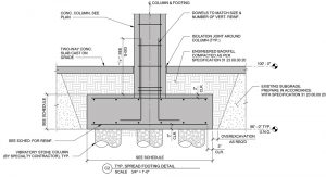
Hybrid Slab-on-Ground
The slab-on-ground also involved an unconventional approach. A hybrid approach with selective soil replacement was used as an alternative to a slab either fully supported on stone columns or structural fill (Figure 3). Compacted structural fill is placed over the footprint of the foundations (supported on stone columns) to act as “rigid” supports, reducing the slab clear span. The slabs have isolation joints around the columns and were analyzed as conventionally reinforced two-way slabs supported on springs representing different moduli of subgrade reaction (150 pci at the foundation and 10 pci for the native soil). Studies were performed to ensure that the maximum live load settlement is less than ¼ inch. The hybrid approach resulted in a thinner slab (7.5 inches) with reduced reinforcement compared to a conventional structural slab-on-ground.
Building Resiliency and Hardening Considerations
DoD buildings are designed with enhanced life safety provisions per the Unified Facilities Criteria requirements, available on the Whole Building Design Guide website (www.wbdg.org). This facility was designed for blast resistance and progressive collapse avoidance (i.e., disproportionate collapse). Design requirements for blast resistance are project-specific and vary for each project.
Facilities with at least three inhabited stories are designed to prevent disproportionate collapse caused by a loss of structural support in accordance with UFC 4-023-03 Design of Buildings to Avoid Progressive Collapse. Multiple design methods are prescribed in that document, and the applicability is determined based on the risk category of the facility. Due to the framing and geometry of this project, the alternate path method was used, which requires the design to consider the removal of individual vertical load-supporting elements around the perimeter of the building and provide a viable alternate load path.
Several structural schemes were evaluated, including perimeter columns with uniform spandrel beams on each floor or a single transfer girder at the roof. The layout of the rooms of the building constrained the location and spacing of the columns. Due to the modular design of the building, removing an exterior column effectively doubled the span length of the beams. Removing outside corner columns created a two-way cantilevered beam condition. Due to architectural constraints, the beam sizes required to support these design options were too large and costly. The final solution developed by the structural design team addressed architectural functionality, minimized material costs, and helped shorten the construction schedule by insetting the perimeter columns and relying on Vierendeel truss action of the masonry walls.
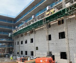
Multi-Functional Masonry Wall
The building’s exterior is constructed with reinforced concrete masonry that also provides resistance to lateral wind and seismic forces. In the original design, the masonry wall also supported the edge of the concrete slabs. However, this required that the masonry wall and concrete frame be constructed concurrently, which would have increased construction time and cost. Concrete columns, inset from the exterior walls, were added so that the construction of the concrete frame was independent of the masonry. Material Unit Lift Enhancers (MULEs), along with jumbo masonry blocks, 8-inch by 32-inch and 74 pounds in weight, were used to increase productivity and safety (Figure 4).
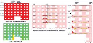
The exterior masonry wall enhances the redundancy of vertical load paths in the building. If a portion of the exterior masonry wall is removed, the loads from the unsupported walls above are redistributed to adjacent wall segments through Vierendeel truss action. Reinforced masonry bond beams at headers, sills, and floor levels and the window jambs are designed for the resultant axial, flexure, and shear forces. Smooth dowels at masonry control joints permit horizontal movement due to temperature and shrinkage while allowing vertical shear load transfer (Figure 5).
The masonry walls are built outboard of the concrete slabs but connected to them to transfer in-plane and out-of-plane loads. The connections allow the masonry to deflect vertically without imposing additional loads on the cantilever slab when a section of the wall is removed. Detailed deflection analyses were performed to verify the slab deflection at the cantilevered slab edges, and, where necessary, the formwork was cambered. The two-way slabs performed well with minimal unanticipated deflections.
Conclusions
The structural design for the project overcame several challenges through close collaboration between the various design team members and the client. The team continually improved the design when opportunities arose, and constant effective communication and timely decision-making were critical in the fast-track delivery of this building, a functional, efficient, and resilient home for our military for many decades to come.■