
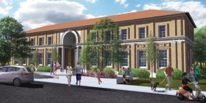
On December 22nd, 2003, the San Simeon Earthquake shook the central California coast damaging two historic unreinforced masonry buildings in downtown Atascadero. One of those buildings was The Printery, constructed in 1915 to house E.G. Lewis’ (the Founder of the Colony of Atascadero) printing operation. Since the earthquake, the building has been abandoned and has suffered from vandalism over the years. In 2016, FTF Engineering was introduced to a non-profit looking to purchase the building to transform it into a community arts building (Figure 1). The non-profit, operating as The Printery Foundation, was able to secure ownership of the building from a public auction in 2017.
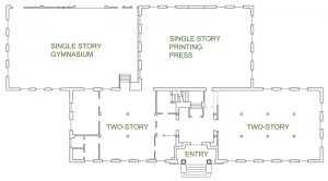
The building was designed by Bliss and Faville Architects out of San Francisco and Engineer M.C. Couchot out of Oakland. The main portion of the building is a rectangular-shaped 2-story structure with a partial basement. At the rear is an original single-story room that housed the printing press and another single-story annex, constructed later, used as a gymnasium for a boy’s home tenant (Figure 2). The foundation, basement, and second floor are of concrete construction with ½-inch-square smooth bar reinforcing with unreinforced brick masonry bearing walls. The first story walls are 4-wythes-wide, and the second story walls are 3-wythes. Roof framing in the two-story section consists of wood rafters spaced at 2 feet on-center, trussed with 1x bottom chords and webs with the hips supported on a steel truss at each end. The single-story portions have hipped roofs framed with long-span steel trusses and wood rafters between. Currently, the buildings are topped with metal roofing over straight sheathing, though there is a reference to a mission tile roof in the as-built drawings.
In 2000, the building was nominated for the National Register of Historic Places and was officially added in 2004. The prominent historical features of the building include the Italian Renaissance terra cotta ornamentation on the exterior of the building and the original Ralph Holmes tapestry murals and marble tile in the central lobby. The building required a seismic retrofit and, because of the historical status of the building, FTF Engineering and Ravatt Albrecht & Associates were able to use the 2019 California Historic Building Code (CHBC) to guide the analysis and retrofit. The retrofit focused on the four items of typical unreinforced masonry buildings known to result in the most damage and loss of life in major earthquakes: in-plane shear capacity of the brick, the out-of-plane bending capacity of the brick, anchorage of the walls to the roof/floor, and weak flexible horizontal diaphragms. The CHBC references Appendix Chapter A1 of the 2013 California Existing Building Code (CEBC). For historic structures, the ideal retrofit minimizes the intervention, maximizes the strength of the existing elements, and adds new elements in specific locations where necessary.
In-Plane Strengthening
Initial retrofit concepts provided by the consultants hired by the city after the earthquake included the addition of narrow shotcrete panels at the corners of the building to serve as new lateral load resisting elements replacing the strength of the original walls. During the schematic design phase, FTF explored this option but determined that collecting the load and dragging it out to the corners of the building would be problematic with the current wood-framed roof to 3-wythe brick wall connection. Shotcrete panels would also add a substantial amount of mass to the structure, impede on the interior square footage, and concentrate the lateral overturning forces resulting in the need to strengthen the existing foundation. With an existing brick shear strength of 100 psi, based on testing and equation A1-4 (2013 CEBC), the team instead decided to explore the option of strengthening the masonry exterior walls to improve their in-plane shear strength. The best option was to team up with Simpson Strong-Tie to utilize their Fabric Reinforced Cementitious Matrix (FRCM, ESR-3506). The FRCM product was chosen over FRP because it is better suited to the unevenness of the brick surface and results in a finished plaster surface that matches what was historically in the interior of portions of the structure. The product will be installed on the interior faces of the walls to avoid disruption of the historic exterior. Heli-Ties will be drilled through the interior wythe of brick at a depth to reach the exterior wythe and a spacing of three feet horizontally and four feet vertically to tie the wythes together. The ties will be staggered vertically to support a diamond-shaped section of the brick wall.
The design process for the use of the FRCM product includes determining the demand and the capacity of the individual unreinforced masonry wall piers and providing this information to the Simpson engineering staff. Simpson then determines the thickness of the cement plaster and the number of layers of carbon fiber grid reinforcement needed to make up for the deficiency. They also provide supplemental calculations and drawings to accompany the SEOR’s design package. For The Printery, the code requires a minimum seismic design lateral force of V = 0.75SDSW/R, with an R = 1.5 for ordinary plain masonry shear walls and a cap of 0.4W for Risk Category III and IV buildings per exception 4 of section 8-706.1 (2019 CHBC). With an SDS of 0.777, the cap of 0.4W controlled the retrofit base shear value.
For example, the wall piers at either end of the building were analyzed using equations Va = vmA/1.5 (equation A1-20; 2013 CEBC) for shear capacity and Vr = 0.9PDD/H (equation A1-21; 2013 CEBC) for rocking shear capacity. The wall piers were found to be controlled by rocking shear with a capacity of 7,315 pounds at the second floor and 10,523 pounds at the first floor. The demand on these panels were 14,665 pounds and 25,157 pounds, respectively, requiring a 1-inch-thick layer of cement plaster and two layers of reinforcement in the second story and 1.5 inches of cement plaster and four layers of reinforcement in the first story. The existing URM walls had sufficient capacity to resist the seismic demand in other locations with longer shear panels. Still, a single layer of fabric reinforcement with 1 inch of cement plaster was specified to help control the cracking of the brick during a seismic event.
Out-of-Plane Strengthening
Supplemental bracing must be provided where the wall height-to-thickness ratios do not meet the requirements of Table A1-B (2013 CECB). The ratios vary based on whether the building has qualifying cross-walls (partitions) or not. The Printery contains large open-span spaces where cross-walls do not exist; therefore, the limits are 13 for the one-story building, 15 for the first story of the two-story building, and 9 for the second story. Analysis revealed that the upper story required bracing. HSS steel strong backs tied into the floor and roof diaphragms with epoxy anchor connections to the brick wall were used to brace the wall out-of-plane. The design lateral force is per A110.1 and meets the spacing/deflection requirements of section A113.5.2 (2013 CEBC).
Out-of-Plane Wall Anchorage
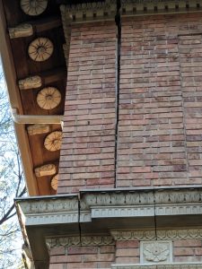
One of the most noticeable deficiencies of the existing building after the earthquake was the inadequacy of the anchorage between the walls and the roof. The walls showed signs of pulling away from the roof in numerous locations and have since been shored to prevent further movement and possible collapse. In the years since the San Simeon earthquake, the crack at the southeast corner of the building appeared to be worsening (Figure 3). In addition to adding shoring, a mason was hired to reconstruct the interior wythes of brick to restore the wall’s structural integrity.
The typical roof-to-wall framing condition in the building has the roof rafters sitting on top of the URM walls with a 2×6 wood plate at the top of the wall. In the one-story portion of the building, the rafters are supported by trusses made up of steel angles spaced approximately 12 feet on-center. The trusses are set into and bear directly on the brick walls with short anchor bolts with limited lateral strength. Beneath each of the trusses is a section of brick wall bulging outward, signifying that the walls were pulling away from the roof during the earthquake. As part of the seismic retrofit, HSS posts have been added underneath any large point loads to help prevent roof collapse if the brick is damaged. The upper roof of the two-story section consists of rafters spaced at 2 feet on-center, trussed with 1x webs, and a built-up 1x bottom chord spliced at approximate third points.
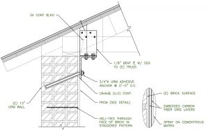
Per the CEBC, it is recommended that the walls be anchored to the roof system at a spacing no greater than six feet on-center, and the preferred method of attachment is to use a through bolt with an anchor plate on the exterior face of the wall. However, since this method would have caused a great deal of disruption to the terra cotta detail on the exterior of the historic building, it was not an option. Instead, a system consisting of epoxy anchors at a spacing of two to three feet on-center was used to reduce the design force per anchor while still significantly improving the expected performance in a seismic event. In most cases, a steel angle was designed to span continuously underneath the existing rafters/trusses with steel angle side plates extending up to tie into the rafters and transfer the out-of-plane forces into the diaphragm. These details aim to simplify construction and reduce field welding wherever possible (Figure 4).
Diaphragm Strengthening
The diaphragm is the “glue” that holds all of the other pieces of the retrofit together; it transfers the loads from the out-of-plane anchors and strong backs out to the newly strengthened shear walls. Per the CEBC Table A1-D, Strength of Existing Building Materials, the existing straight sheathed diaphragms are adequate for 300 plf but, with the heavy weight of the building, it was determined that the minimum diaphragm force was 323 plf and a maximum of 686 plf. Since the metal roofs are at the point of needing replacement, ½-inch plywood overlay will be used to strengthen the diaphragms with nail spacing and patterns varying based on the required capacities. The plywood will be applied directly over the 1¼-inch sheathing, and 16-penny nails have been specified to achieve the required penetration. As an alternative, FTF provided an option for a diaphragm screw since the age of the wood framing can make it difficult for nails to penetrate the hardened wood.
Summary
While the deficiencies of most URM buildings are similar, the details of the retrofits are all very unique to the individual buildings. The Atascadero Printery building had its own set of challenges, including the irregular geometry, the historic nature of the project, and working with a non-profit tasked with raising money to save the building. The first two items were solved with engineering and teaming with companies like Simpson Strong-Tie. The last led FTF to use creativity to design connections that do not require skilled tradespeople, permitting as much volunteer labor as possible to achieve the retrofit and stay involved in the organization’s fund-raising efforts. If you are interested in supporting the project and saving a piece of history, please see https://atascaderoprintery.org.■