
Member and Connection Design Considerations
As architects, owners, and contractors continue to push the limits of wood-framed residential construction, manufacturers have responded by providing an increased number of specialized wood and connector products. However, in addition to specialized wood products, these same complex residential projects increasingly rely on reinforced concrete and structural steel to achieve the intended design, frequently necessitating custom connections. This article reviews the various wood products available today for framing floors and roofs and discusses connection considerations to wood, steel, and reinforced concrete.
Engineered Wood Products
Though sawn lumber remains a common choice for traditional wood-framed building construction, engineered wood products help architects, engineers, and contractors provide wood solutions to a variety of projects where traditional sawn lumber could not otherwise be considered. Typical products include I-joists, glue-laminated timber (glulam), structural composite lumber such as laminated veneer lumber (LVL) or parallel strand lumber (PSL), and metal-plate-connected wood trusses (MPCWT). In addition, cross-laminated timber (CLT) is an increasingly popular product in commercial construction but is not discussed in this article.
I-Joists
Prefabricated wood I-joists are an engineered wood product comprised of two flanges and a continuous plywood web. The flanges are typically dimensional lumber or laminated veneer lumber, and the web is typically traditional plywood or oriented strand board (OSB). I-joists are commonly available in depths of 9½, 11⅞, 14, and 16 inches, though available up to 24 inches from certain manufacturers. Flange widths vary from 1¾ to 3½ inches. Compared to solid sawn lumber, I-joists are lighter, stronger, and stiffer for equivalent depths. Manufacturers have developed prefabricated connector products specific to I-joists. Though the adhesives used in the manufacturing process are rated for temporary moisture exposure, they are not intended for prolonged or permanent exposure to moisture. Therefore, they are generally more susceptible to moisture damage than traditional sawn lumber.
Glue-Laminated Timber
Glulam timber is an engineered product made by bonding individual pieces of lumber, typically, along their flat face. Individual pieces of timber can be end-joined to create continuous laminations. Laminations are then face-joined to create a finished wood cross-section. Individual laminations can, and often do, vary in strength from the strongest laminations at the outer surfaces to weaker or lower quality wood at the neutral axis.
Glulam comes in a variety of species with varying glue and preservative treatments. Glulam beams offer higher strengths and more dimensional stability than solid sawn lumber, primarily due to their manufacturing process. They use dimensional lumber typically dried to a moisture content of 16% or less. Glulam beams can also be created in custom shapes, including curved, to create unique profiles, and are often used in exposed, vaulted ceiling applications. Glulam beams are commonly available in widths of 3⅛, 3½, 5⅛, 5½, and 6¾ inches, but many custom manufacturers can create unique sizes and shapes.
Structural Composite Lumber
Structural composite lumber is a class of engineered wood product that includes LVL, PSL, laminated strand lumber (LSL), and oriented strand lumber (OSL). They are often used as headers or transfer girders, or in long-span beam conditions. PSL can also be used as posts. Structural composite lumber is created by layering stress-graded wood veneers, strands, or flakes with moisture-resistant resin. The layers are then molded into blocks and sawn to specified sizes. Like glulam, structural composite lumber members are more dimensionally stable and have higher, more uniform strength properties than traditional sawn lumber. Though the adhesives used in the manufacturing process are rated for temporary moisture exposure, they are not intended for prolonged or permanent exposure to moisture. Therefore, they are generally more susceptible to moisture damage than traditional sawn lumber.
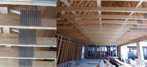
Metal Plate Connected Wood Trusses
Metal plate connected wood trusses consist of individual timber elements connected by punched sheet metal plates, pressed into each face of the jointed connection. They are a popular engineered solution used widely in floor and roof construction. MPCWT offers a high strength-to-weight ratio, can span 25 feet or more and can accommodate various roof profiles. The deflection behavior of metal plate connected wood trusses depends on connector plate installation. These systems are often more susceptible to floor bounce and vibration than a traditional sawn lumber system. Metal plate connected wood trusses are typically specified with design criteria by the project structural engineer of record (SEoR) and designed by the manufacturer and their Specialty Structural Engineer (SSE). In specifying the trusses and outlining the design criteria, the SEoR must be clear on who will be responsible for the permanent bracing of the installed trusses. The authors typically require permanent bracing to be designed by the manufacturer’s SSE but provide details of the permanent connections at each bearing location in the base building drawings.
Prefabricated Connectors
Wood-to-Wood Connections
In modern wood-framed construction, it is common to see a variety of sawn lumber and engineered wood products on the same project. However, when combining sawn and engineered wood in the same floor system, care should be taken as they can have different moisture contents and corresponding shrinkage. Sawn lumber, I-joists, or metal-plate-connected wood trusses often comprise a building’s primary floor framing system. Glulam or structural composite lumber beams often function as headers and transfer girders. In some applications, glulams are used as exposed elements due to their aesthetic qualities.
Manufacturers have developed prefabricated metal connector products to efficiently facilitate connections for the variety of sawn and engineered wood elements. These connectors accommodate a range of framing applications. They include options to mount on member-side faces or top flanges, connect skewed and sloped members, and conceal connector flanges where desirable aesthetically or required geometrically. Prefabricated metal connectors are efficient to install due to their template holes for nails, screws, and bolts. They are also easy to determine based on load demands and easy to specify with manufacturer tabulated permissible loads and logical naming conventions.
Designers need to consider the required size, quantity, and embedment of the fasteners and confirm they are compatible with the pieces to be connected as well as other connections in proximity to the connection being considered. Some manufacturers also offer replacement fastener options with load adjustment factors for commonly used nails and screws.
Wood-to-Steel Connections
Steel is typically introduced in an otherwise wood-framed project to provide greater strength or stiffness in a depth-constricted area, to support discontinuous loads from multiple floors above, or to create a larger open area than can be efficiently developed in wood. Steel beams and girders introduced for these purposes are typically supported on reinforced concrete foundation walls or steel columns. An important design consideration for these types of connections is the differential movement between the wood and steel, as wood will expand and contract with seasonal ambient moisture variations. In contrast, steel will remain relatively dimensionally stable. Steel connections that confine the wood can result in splits, cracked finishes, and potential connection failures.
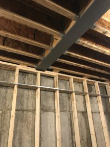
Wood-to-Steel Beam Connections
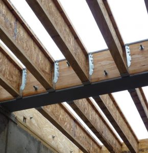
Wood framing may be connected to steel beams in three primary ways: 1) face mount hangers connected to the side face of wood blocking attached to the web of the steel beam, 2) top flange mounted hangers connected to wood nailers affixed to the beam top flange, and 3) top flange mounted hangers welded to the top flange of the steel beam.
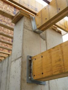
Face mount hangers are affixed to continuous wood blocking bolted to the web of the steel beam. Depending on the size of the steel beam and the depth of the wood element, multiple layers of continuous wood blocking may be required. Engineers must design the wood blocking attachment to the steel beam for the required joist loading (gravity, lateral, and uplift), as the joist hanger manufacturers specifically do not qualify those attachments. Additionally, wood blocking attachments, typically through bolts and face-mount hangers, need to be coordinated to avoid conflicts between bolt heads, nuts, and exposed bolt end and joist hanger flanges. Finally, certain hanger nailing requirements may require at least three inches of blocking.
Top flange mounted hangers can be used with continuous wood plates bolted to the top surface of the steel beam top flange. Depending on the width of the beam and the type of hanger, the wood plates may need to be cut to match the steel beam flange width. Engineers must design the wood plate attachment to the steel beam to transfer the required loading to the steel beam. Wood plates can be bolted to the steel beams with pre-welded threaded rods, through bolts, or powder-actuated fasteners for thinner steel flanges. As with face-mount hangers, coordinating the wood plate attachment with the top flange hangers is essential to prevent installation conflicts. Some hanger nailing requirements may necessitate at least three inches of wood plate depth.
Certain top flange-mounted hangers can be welded directly to steel beams. This can be advantageous when a deep steel beam is required in a limited floor-to-floor height or depth-limited ceiling space. However, for plywood sheathed floors, consideration must be given to how the edges of the plywood diaphragm will attach to a steel beam to transfer diaphragm force if required. This is especially important where the steel beam is in place to transfer a discontinuous shear wall above. Powder-actuated fasteners, carriage bolts, or sex bolts are options. Top flange mount hanger welds to steel beams are typically ⅛- to 3⁄16-inch fillet welds with minimum lengths specified by the manufacturer. Wood blocking is not typically required behind the welded joist hanger. However, web stiffeners may be required for the steel beam based on loading configuration, the loading magnitude, and steel flange and web thicknesses. Depending on the type of construction, welder quality can vary widely. Therefore, engineers should consider both the quality of welding available and the additional labor/trade required when specifying top flange mounted, welded hangers.
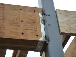
Wood-to-Steel Column Connections
When steel beams are introduced to a building in the floor framing, it frequently results in steel columns being introduced as well. For this discussion, the authors are not including lally columns used in traditional basement construction. Steel columns can be wide flange sections, but they are frequently hollow structural sections (HSS) to fit within wood stud framed walls.
Sometimes, wood elements connect to steel columns by prefabricated welded joist hangers. Depending on the column flange width, welded joist hangers attach directly to a base steel member and can have concealed or extended flanges. For HSS columns, the joist hanger width should be coordinated with the workable flat-tube dimension and not the nominal dimension. The welds are typically 1⁄16-inch fillet or flare bevel groove stitch welds, symmetrically placed. The small weld size prevents burn-through of the metal hangers; as noted above, this requires skilled, qualified welders. Therefore, even for small projects, specifying an AWS-certified welder to perform these welds is valuable.
Not every joist hanger can be welded, so check the manufacturer’s product literature before specifying a welded joist hanger. The manufacturer’s product literature will also provide the tested weld sizes and weld configurations along with their allowable load carrying capacities. The load-carrying capacity is typically the lesser value between the joist hanger capacity and the weld capacity. In seismic regions, consideration should be given to lateral forces at these hangers since manufacturers typically do not publish allowable lateral values for weldable joist hangers.
As an alternative, custom wood-to-steel connections can also be designed and utilized for situations where load demand, connection geometry, or architectural requirements preclude the use of readily available prefabricated joist hangers. In this case, the options are endless. However, the downside to these connections is the high material and labor costs and engineering time relative to traditional joist hangers. Therefore, custom hangers should be designed by the structural engineer and not delegated to the contractor.
For all welded connections, base metal preparation is key to a successful connection. Base steel that has surface rust should be cleaned before welding. Welding over paint is discouraged by welding codes and can cause unsightly blemishes, release toxic fumes, and compromise the quality of the weld. Steel that has been primed requires cleaning prior to welding. Engineers should recognize the potential for less sophisticated welders in residential construction and be clear in welding requirements. Consider requiring weld-specific inspections by qualified inspectors for critical welds on a project.
Wood-to-Concrete Connections
Designers must pay special attention to moisture, where wood is attached to concrete elements, typically at foundation walls and footings. Wood sill plates and rim boards attached to concrete foundation walls are typically pressure treated to protect against moisture migration from the concrete. The coordination of concrete anchors, post bases, steel embed plates, beam pockets, and ledges is also important. Locating these elements before concrete foundation placement requires up-front coordination but saves time and cost overall for the project. If the contractor prefers to post-install these anchors, they should scan for reinforcement before drilling.
Wood nailers and plates are typically anchored to concrete through cast-in threaded rods or J-bolts. They are often doubled up to provide adequate nailing for plywood-sheathed shear walls and diaphragms. Where double sill plates or rim boards are used with cast-in anchors, contractors must coordinate the anchor’s location and extension beyond the concrete surface to ensure adequate thread length for the nuts.
Summary
As manufactured wood product options continue to increase, architects, contractors, and engineers should understand the advantages and disadvantages of each system, material, and product option. There are numerous configurations in which wood elements connect to other wood elements, structural steel, and concrete. Engineers can design with prefabricated and custom connectors and create ever-more complex and exciting structures. However, to do so successfully, engineers need to understand both the opportunities and limitations of each material product, the contractor’s experience with different systems, and the available trade people.■