
A Story of Transfer Girders
The Near Capital Region (NCR) around India’s capital, New Delhi, witnessed a decade-long construction boom starting in 2008. Several high-rise apartments were constructed to cater to the growing need for housing in Noida, which was followed by new office construction to lure large corporations away from the urban sprawl of New Delhi.
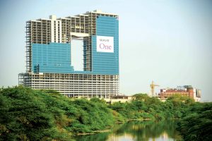
Wave One is a $276 million, 41-story mixed-use building with more than 2 million square feet of floor area located in the heart of Noida. It includes three levels of retail, two-story cinemas on the fourth floor, seven levels of parking above the cinema, and three levels of underground parking for a total of 2,600 cars. In addition, an extensive amenity deck, tennis courts, and a health club on Level 15 serve the tenants of the 26-story office building that rises above the podium.
The structure has a footprint of 528 feet by 228 feet on the podium levels and is constructed with no expansion joints. The building is characterized by a large rectangular aperture created to allow the “flow of energy” through the property. This aperture breaks the large office mass into two distinct towers, which are reconnected between Levels 32 and 41.
The project is located in a region of moderate high seismicity, requiring special detailing for concrete elements, including additional checks for deformation compatibility of the slab-column gravity system. Shear walls at the cores provided lateral force resistance.
The design is in accordance with India’s National Building Code (NBC) and other applicable local codes. Due to the building’s height and unique geometry, a wind tunnel study was conducted to determine the structural loads and occupant comfort.
Zero Lot Line Construction
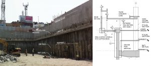
To maximize the building’s footprint, the basements are constructed with zero lot lines using a contiguous bored pile (CBP) wall earth retention system tied back using post-tensioned soil anchors until the basement slabs were installed. Traditionally, concrete retaining walls are constructed to act as the permanent structure in front of these piled walls. However, on this project, these CBP walls also act as a permanent earth retention system and support the basement slabs along the perimeter. In addition, masonry walls are built in front of the piled walls to conceal the drainage channels. This scheme resulted in a significant cost saving.
Post-Tensioning as a Driver
Concrete is the material of choice for constructing buildings in India. When speed is a primary driver, as it was for this project, post-tensioned slabs and beams reign supreme. This is due to the load-balancing provided by the post-tensioning tendons that allow formwork to be removed and reused as soon as the tendons are stressed. When this project was conceived, post-tensioned concrete for buildings was in its nascency in India. It required a collaborative effort between the design team, contractor, and developer to devise the layout of vertical framing organized around an efficient post-tensioned slab system.
The mixed-use building is apportioned into various uses such as parking, retail, offices, cinemas, outdoor amenities, mechanical floors, etc. The multi-story parking levels determined the layout of the columns in the podium, which, in turn, resulted in a square grid of 28 feet by 28 feet for the majority of areas, except for some longer spans at drive aisles. This layout also allowed the columns to continue vertically through the office levels with minimal impact. The typical slab thickness is 8 inches at the parking and office levels, while the retail levels have a thicker 9-inch slab.
Traditionally, buildings in India are constructed with 2 to 3 inches of screed on top of the structural slab to allow for the lack of sophisticated finishing methods and allow tenants to pick their flooring as part of tenant improvement. However, on this design-assist project, it was decided to forgo the layer of screed on the parking levels due to the contractor’s ability to deliver a superior finished surface. In addition, the removal of the screed reduced the seismic mass of the building and helped to optimize the post-tensioned slab.
The project’s scale and varied occupancies triggered a “Type 1” construction in accordance with the NBC, necessitating a 3-hour fire rating for the slabs. The conventional practice was to consider the concrete clear cover of 1⅜ inches to the post-tensioning duct even though the tendons are grouted and are often higher in the duct at midspan. BASE collaborated with the PT supplier to determine the elevation of the tendon within the duct, thereby gaining valuable drape in the tendon profile while still meeting the clear cover intent of the code.
Transfer Girders Galore
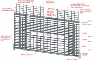
At Level 4 of the podium, above three levels of retail, the floor area was allocated for cinemas that required 56 feet by 84 feet of double-height, column-free space for each of the five cinemas. This could only be achieved through a five-span shallow post-tensioned transfer girder that spanned 56 feet while supporting seven levels of parking, one level of office, and one level of outdoor amenities. A portion of the office tower also hovered above the cinemas, requiring a different strategy to transfer the tower columns.
The limited height available over the cinemas required a double transfer beam to support the office tower columns spanning between Levels 15 and 41. This was achieved by introducing one-story-deep transfer girders between Levels 14 and 15 and using the transfer beam over the cinemas to only support the podium loads.
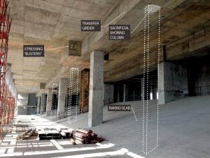
Due to the unique nature and length of the 280-foot multi-span transfer girder over the cinemas that were required along two column lines, the design team collaborated with the PT supplier to stress the tendons outside the cross-section of the girder. This facilitated pour strips and allowed the entire girder to be constructed simultaneously while also providing intermediate stressing to minimize post-tensioning losses. The external stressing strategy is often used in bridges but is not very common in buildings. BASE worked closely with the PT contractor and formwork subcontractor to minimize the number of reshoring levels by continuing the column removed in the cinemas as a low-strength sacrificial column supporting the transfer girder. This strategy enabled the early removal of beam formwork and three levels of reshoring below the transfer girder.
Due to the zero lot line construction, the parking ramps are integrated within the building footprint. Two octagonal spiral ramps, one on each side of the building, provide vertical circulation for the parking levels. The ramps stop at the underside of Level 13 with 27 levels above it. Like the columns transferred over the cinemas, the tower columns above the ramp are supported on 6-foot-deep transfer girders extending between Levels 14 and 15. The total length of the transfer girder on Level 14 is 310 feet.
The building’s characteristic rectangular aperture measures 200 feet by 103 feet and extends between Levels 15 and 32. The aperture is framed at the top by offices between Levels 32 and 41. The top of the building steps up from one end of the building to the other. The structure above the aperture is supported by three profiled post-tensioned girders that span 112 feet between each tower. These sizeable concrete transfer girders were partly conceived due to the contractor’s desire to use a tried and tested construction methodology instead of introducing structural steel trusses. The contractor’s message to the design team was, “No Discovery Channel stuff, please.” However, the concrete option came with its own challenges from transfer girders that are 3.3 to 5 feet wide and constructed at 200 feet in the air. Due to the immense weight of the three transfer girders and the associated formwork requirements, the girders were shaped to reduce overall weight such that it was 20.5 feet deep in the middle to maximize drape and stiffness for the 112-foot span and 15 feet at the ends to satisfy shear requirements. Despite the shape optimization, the weight of wet concrete during placement would be problematic.
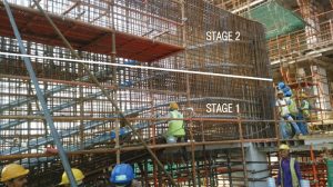
BASE worked with the contractor and PT supplier to construct the beam in two segments with a horizontal construction joint with layered tendons that could be independently stressed. Once stressed, tendons in the lower half were designed to support the weight of the upper half during construction. Tendons in the second half were profiled such that maximum drape was utilized for final loading. The overall process was done in six stages: three bottom segments and three top segments.
Conclusion
A 2 million square foot high-rise project with multiple occupancies often comes with many challenges that require creative engineering solutions and close collaboration with the architect and other consultants. Post-tensioning often helps to simplify many of these problems by allowing for the removal, transfer, and shifting of columns and allowing slabs to span longer where required, giving the architect the desired flexibility.■
Project Team
Owner: Wave Infratech
Structural Engineer of Record: BASE
Architect of Record: Nostri Architects
Design Architect: BBG-BBGM
General Contractor: Leighton-Infra Joint Venture
Wind Tunnel Consultant: RWDI