
Part 1: Building History and Structure
This four-part series discusses the adaptive reuse of the Witherspoon Building in Philadelphia, PA. Part 1 includes the building history and description of the structure, including previous structural additions and alterations. In addition, numbered photos are provided with the print version of the articles, and additional lettered photos are provided with the online version of the articles.
Building History
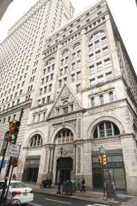
The 11-story Witherspoon Building (not including full and sub-basement levels) is on the National and Philadelphia Registers of Historic Places. It is considered Philadelphia’s first “skyscraper” and was constructed with Carnegie Steel beams between 1895 and 1897 for the Presbyterian Board and Sabbath School for use by various Presbyterian Church groups (Figure 1). As indicated on the available historical Sanborn Map for the building, the exterior brick masonry curtain wall varies in thickness from 28 inches to 12 inches, from bottom to top of the exterior façade, respectively. The Sanborn Map also indicates that the floors and roofs were framed with hollow clay tiles. The building was named for John Witherspoon, the first president of Princeton University (then known as the College of New Jersey). It was designed by Architect Joseph M. Huston, a graduate of Princeton, and constructed by William Steele and Son, Carpenters and Builders.
Original Structure
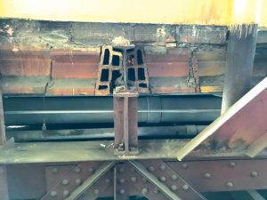
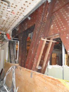
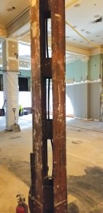
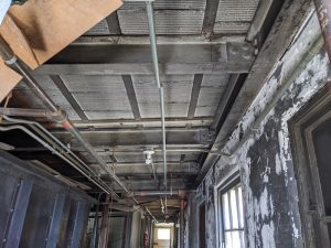
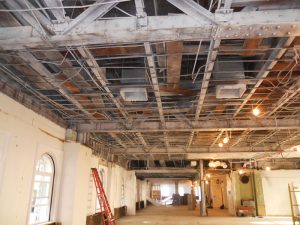
In general, the floors and main roof are constructed with 12-inch-deep, hollow clay tiles arranged in end-to-end, flat arch construction with voussoir, or “keystone,” hollow clay tiles placed parallel to and on each side of the supporting 12-inch-deep Carnegie Steel B section “I” beams (Figure 2). The voids of the keystone tiles are also oriented parallel to the beam span and therefore perpendicular to the main arch tiles. This is referred to as a combined end and side configuration. The beams are typically supported by built-up riveted steel plate and angle girders (Figure A) or steel B section girders. Built-up, story-high, riveted parallel top and bottom chord steel transfer trusses (Figure 3) support the south portion of the 4th and 5th floors and the columns that support the floor and roof framing above. Also, similarly constructed roof trusses clear span across the north end of the building above the 11th floor. In addition, except at the mechanical roof penthouse and standalone 1st floor shed, the main building columns consist of built-up riveted angle sections known as Gray columns (Figure 4).
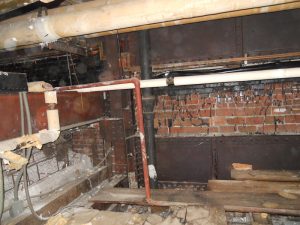
Portions of the basement floor framing over the sub-basement were constructed with brick arches spanning between steel beams. In contrast, the roof over the mechanical penthouse was constructed with 4-inch hollow clay “book” tiles that simple span between inverted tee or “bulb” steel purlins supported by steel B section beams (Figure 5). Round, hollow cast iron columns support the beams. There is also an ornamental, cast-iron framed, single-story gabled roof structure that occupies what was originally an open courtyard area at the 1st or ground floor on the west side of the building.
Details of notable original documented structural features of the building include:
Gray Columns
It is interesting to note that fabricated columns in the Witherspoon Building appear to have been used because the engineer and contractor had not transitioned from employing rolled steel “I” sections as horizontal beam elements to vertical column elements, as is done today. The Gray columns used in the Witherspoon Building were a patented section that could be fabricated with structural shapes, in this case, angles that any steel mill could roll.
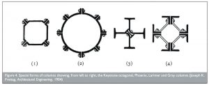
Similar patented sections, like Phoenix columns, could not be fabricated with rolled sections. Therefore, because Carnegie Steel supplied the beams for the building, it was assumed that the Gray column components were likewise rolled by Carnegie (cross-section (4) in Figure B).
In addition, it was confirmed via field measurements that the vertical angles used in the Gray columns conformed with the available standard angle sizes provided in the 1896 Carnegie Steel Pocket Companion. It is also interesting to note that both the Fisher Building in Chicago and Guaranty Building in Buffalo, constructed at the same time as the Witherspoon Building, used Gray columns.
Main Roof Trusses
At the north end of the building, to provide a column-free space at the 11th floor, 4-foot-deep Warren steel trusses, fabricated with angles, plates, and rivets, were constructed to clear span from the east to west sides of the building (Figure C). The trusses support the main roof framing, the original mechanical penthouse floor and roof framing, and the 11th-floor walk-on attic/ceiling in this same area of the building.
4th Floor Transfer Trusses
At a portion of the south end of the building, to provide a partial column-free space between the 2nd and 4th floors, story-high steel trusses, fabricated with angles, plates, and rivets, were constructed to span from east to west across the main rectangular footprint of the main building. The trusses support all floor and roof framing at and above the 4th floor in the area impacted by the same transfer members. The open area below the transfer trusses was initially used as a large assembly space called Witherspoon Hall.
11th Floor Ceiling
Because the story height from the 11th floor to the main roof structure is almost equivalent to a two-story space, steel beam framing was provided to support the 11th-floor plaster ceiling, which also served as an accessible attic/plenum space. This same ceiling framing extends over the entire building footprint and serves as the floor framing for the original mechanical penthouse. The attic/plenum is accessible from a spiral staircase adjacent to the passenger elevators that extends from the 11th floor to the main roof and a knee wall hatchway in the original mechanical penthouse. A portion of the attic/plenum was also originally accessible from the stair located in the northwest corner of the building.
Structural Additions
At some point during the life of the building, several structural renovations and additions were constructed. The exact age of these renovations is not known and include the following:
2nd Floor Mezzanine and 3rd Floor Infill
A mezzanine above the 2nd floor and infill framing at the 3rd floor were constructed between the 2nd and 4th floors at the south end of the building, within the same large assembly space originally called Witherspoon Hall. According to the National Register of Historic Places (NRHP) Inventory Nomination Form, this portion of the building may have been constructed in the early 1960s.
The existing 2nd-floor mezzanine and 3rd-floor framing consist of a 2½-inch concrete slab on a 1½-inch cellular metal deck for a total of 4 inches. Historical information obtained from the Steel Deck Institute (SDI) indicates that the metal deck was a Q-Deck product manufactured by H.H. Robertson Company. The slab spans between W12 purlins and W14 girders. The 3rd-floor infill was reused for the latest adaptive reuse project; however, the 2nd-floor mezzanine was demolished to make room for a 2nd-floor loft that was subsequently not incorporated into the final project.
Passenger Elevators Upgrade
According to the NRHP Inventory Nomination Form, the original passenger elevators were upgraded in the early 1960s. However, a comparison of the Sanborn Map for the original facility to the current building indicates that the only structural manifestation of this renovation appears to be the construction of a rooftop machine room penthouse located above the original elevator shafts (Figure D).
Freight Elevator Upgrade
Similar to the passenger elevators, it appears that the freight elevator was upgraded during the life of the building. The structural renovations included a new machine room penthouse supported by rooftop dunnage beams that span between the main building columns, except at the south end of the eastern beam, which is supported by the northernmost roof truss (Figure E). In addition, drawings provided by the Otis Elevator Company, dated 1950, indicate that the original two shafts at this elevator, shown on the Sanborn Map, were converted to a single shaft elevator as a part of the renovations.
Northwest, Main, and South Stair Renovations
The extent of structural renovations that occurred at the top of the referenced stairs is unclear; however, the current configuration of the roofs of these stairs appears different from that shown on the Sanborn Map. In addition, it appears the southern stair may have been renovated as a part of the 2nd-floor mezzanine and 3rd-floor infill framing in the 1960s.
Roof Top Dunnage
At some point during the life of the facility, steel dunnage frames were constructed above the south end of the main roof that are supported by steel wide flange columns that post down to the top of the original main building columns. There are two sets of dunnage frames that interface slightly. The southernmost dunnage frame supports an active prefabricated electrical room, while the northern dunnage frame supported mechanical cooling towers that were replaced as a part of the adaptive reuse project.
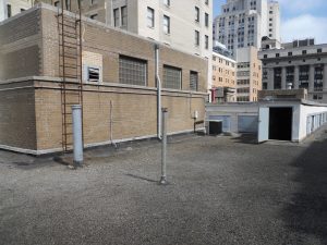
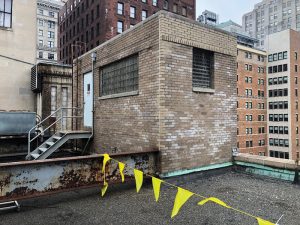
Mechanical Penthouse
A one-story mechanical penthouse was constructed southwest of the passenger elevator penthouse sometime during the life of the facility. The space is accessed from the same spiral staircase described for the 11th-floor ceiling and provides the only access to the top of the main roof through the penthouse. The floor is framed with a solid, one-way 6-inch concrete slab supported by steel wide flange beams at an elevation slightly above the main roof level, which created a shallow crawl space that can be accessed via two floor hatches. The floor framing is supported by steel columns that extend down to the main building columns.
The roof consists of precast concrete planks supported by open web steel joists that clear span to steel beam and column supports at the perimeter of the penthouse. A portion of the penthouse was also constructed above a large mechanical opening that was partially enclosed for the full height of the shaft with hollow, masonry pyro-bloc units that contain asbestos. This same shaft opening was infilled at each affected floor level as a part of the adaptive reuse.■
The author would like to thank Sara Wermiel, Ph.D. as the source for most of the historical information provided in Part 1.
Part 2 of this series will provide more details on the adaptive reuse and structural investigation.