
Building codes and standards are typically enacted in response to hazardous situations that threaten public health, safety, and welfare, or to natural disasters such as floods, fires, and earthquakes. Fire protection was the first major issue leading to the establishment of early building codes in the United States. In 1896, the National Fire Protection Agency (NFPA) was founded to establish uniform sprinkler standards for the mills and warehouses in the Northeast. First published in 1897, NFPA standards were used until the 1950s. Modern structural related building codes were first introduced in the United States around 1900 in cities such as New York and Chicago.
Most building codes are updated on three- to five-year cycles to incorporate new knowledge from research as well as in-service occurrences. Keeping codes current to existing knowledge for new construction can create confusion about their applicability to existing structures, particularly historic structures. An unintended consequence is that when codes are taken at face value, they often discourage rehabilitation projects due to inconsistency in how the codes apply to rehabilitation compared to new construction.
Masonry Façade Rehabilitation
Applying modern structural evaluation criteria and contemporary standards/codes to historic masonry façades without rational, practical engineering judgment can result in overly conservative analysis and unnecessary repairs. Often, distress in historic masonry façades is caused by corrosion of the underlying steel support. Still, there are also instances when the cause of the distress is not specifically corrosion-related. Understanding how these historic masonry systems behave is critical to understanding appropriate repairs. In addition to corrosion, masonry distress can result from unaccommodated movement, unit geometry, variable support, modified load paths, poor installation, field modifications, and previous inappropriate repairs. Historic masonry façades were typically constructed with corrodible metals and without flashings. As a result, the support components are highly susceptible to corrosion. It should be understood that all of the conditions listed above, and resulting distress, will be exacerbated by the accumulation of corrosion scale. The following examples illustrate some of the common distress conditions that are often encountered and sometimes misinterpreted.
The Distress of In-Plane Façade Elements
In-plane elements refer to units or assemblies within the plane of the main façade and can be grouped into three categories: intermediate support, hung elements, and combined support assemblies. Each of these support conditions presents potentially unique distress scenarios related to the structural support of the units and, therefore, will potentially require different repair approaches.
Intermediate Support Elements
These assemblies or units are supported at floor lines, window/door heads, or corners of the building. Distress at intermediate supports is often related to the configuration of shelf angles and the lack of accommodation of general building movements. Distress is often the result of discontinuous gravity support of the masonry. Examples include corners of the building where the shelf angles from the two different façades do not align or are held short of the corner (Figure 1), or discrete lintel elements that are limited to openings rather than continuous shelf angles extending around the perimeter of the building. These conditions can result in vertical cracking due to the change in relative stiffness of the support. Additionally, distress can be the result of unit geometries, unanticipated load paths, inadequate bearing, construction tolerances, and inadequate or inappropriate field modifications to the masonry units themselves.
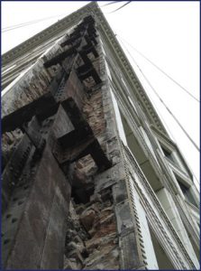
In the case of continuous piers and corners, the effect of differential movement between the masonry and the underlying structure can result in significant internal stresses within the cladding system leading to localized crushing, in-plane shear cracking, vertical cracking, and outward displacement of units. The manifestation of this distress typically occurs where the masonry is restrained, such as at supports within piers or at intersecting walls at the corners of the building.
Masonry cladding with distress related to discontinuous or lack of adequate intermediate support generally requires repairs. Often, these repairs address the structural support by removing masonry units and repairing, supplementing, or replacing the steel to establish adequate bearing.
Hung Elements
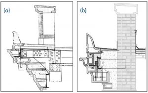
Hung elements typically exist at openings in the façades, most commonly windows. The individual units are hung with j-hooks and rods or other anchors from the supporting structural steel above (Figure 2). Distress in hung components is often related to corrosion of the anchorages rather than other structural issues. Corrosion related distress at hung elements needs to be addressed to maintain adequate structural support due to the lack of redundancy of support with hung elements.

Non-corrosion related distress is typically associated with deflection of the units due to the flexibility of the support. When displacement of the supporting lintel is observed, particularly at larger openings, it does not necessarily warrant repairs. If the condition of the steel can be verified and it is determined to be serviceable, deflections may be a result of installation tolerances, catenary behavior, inelastic bending, or building movements. Often repairs are not necessary to “correct” the deflections. Generally, the masonry at these locations will behave as an arch in addition to the support provided by the hanger elements. Thus, while the hung assemblies may not work “on paper,” they remain functional and typically can be “repaired in kind,” as shown in Figure 2.
Combined Support Elements
Elements with combined support are units that are located at the interfaces of piers and spandrels or two different support conditions. Distress at masonry units with combined support is often a result of the load sharing between support elements, i.e., units that extend between the lintel and the piers, sills and piers, etc. Differential loading of individual units can result in cracking. Examples include the corners of the windows where lintel and units extend between the piers and spandrel area, causing differential stress within the unit. The portion of each unit within the pier is subjected to significantly higher compression stresses and restraint than the portion within the spandrel. This differential stress within the same unit, as well as general building movements, often causes cracking at the transition of support conditions. In glazed masonry products such as terra cotta, the stress occurring within these units is often manifested by crazing in the glaze, which indirectly illustrates the alternate load path (Figure 3).
Masonry with distress related to elements with combined support often does not require structural repairs. The configuration of the existing units and structural support is challenging to change, and, as long as significant out of plane movement or displacement is not observed, the associated cracking of the units is essentially the masonry system’s way of providing stress relief. Minor repairs, including treating cracks and adding supplemental in-situ pins, are generally the methods necessary to limit water infiltration and secure the individual pieces. Repairs that are often performed include installing supplemental steel support at every floor line and other approaches that change the unit geometries and potentially require extensive rebuilding and unanticipated future issues. Often, these repairs are not necessary due to the slip plane detailing that was often used historically.
Distress of Projecting Façade Elements
Projecting elements generally refer to façade assemblies that are exposed on three surfaces, including 1) horizontal projections such as cornices and watertables, and 2) vertical projections such as parapets and balustrades. These elements present specific distress scenarios particularly related to the structural support of the assemblies and often require extensive repairs, which makes meeting current structural regulations challenging.
Projecting masonry elements that experience cracking and displacements are likely the result of accumulated stresses along the length of the façade. These stresses are mostly due to unaccommodated thermal and moisture movements of the cladding materials, as well as differential movements between the masonry and the underlying structure.
Fired clay products expand during the first few years after fabrication due to the absorption of moisture from the atmosphere. The rate of expansion slows as the moisture content of the masonry material equalizes with the atmosphere. Over the service life of a building, the façade materials also expand and contract due to thermal cycles. If the moisture expansion and thermal expansion are not accommodated, internal stresses accumulate within the cladding system. These internal stresses often result in cracking and displacement in long continuous bands of masonry, such as parapets, cornices, watertables, and continuous spandrel areas. These conditions are most pronounced at corners where the accumulated movements occur in two directions.
Cornices And Watertables
Cornices and watertables are continuous projecting horizontal bands around part or all of the perimeter of the building. Distress at these locations is often related to corrosion of the anchorages (similar to hung elements), and cyclical movements.
The non-corrosion related distress is typically associated with displacement of the units due to the flexibility of the support, unaccommodated expansion, original construction techniques (including filling units), and lack of maintenance or improper maintenance over the years. While the flexibility of the system generally does not work “on paper” with current code-prescribed loadings, in some instances – such as seismic loading – the flexibility may improve the performance of the system. Historically, cornice systems were designed empirically, often with convoluted load paths, as shown in Figure 4a, and it is, therefore, challenging to “upgrade” the support to current standards. Often, the most appropriate and rational approach for cornice repairs is “in-kind” replacement using non-corrodible elements for the anchors, hangers, etc., as shown in Figure 4b. The failure mechanisms in this instance were due to the units 1) having been backfilled with concrete, and 2) lack of maintenance, which contributed to moisture infiltration and corrosion of the support elements. Many drastic “repairs” were made to cornices and watertables as they became maintenance concerns. In extreme instances, repairs included removal or partial removal of the elements to meet current regulations and protect public safety.
Parapets
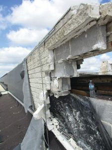
Historic masonry parapets typically are multi-wythe and are rarely reinforced. Non-corrosion related distress at parapets is generally related to bowing, bulging, and displacements, which are often a result of the stresses from unaccommodated expansion and cyclical movement. General deterioration due to being exposed on three sides, and subsequent increased freeze-thaw exposure, can also contribute to these conditions. In some instances, non-corrosion distress is exacerbated by previous repairs such as installed flashings that introduced a slip plane into the system without accommodation of anchorage of the portions of the wall above and below the slip plane, as illustrated in the example from a 1960s parapet wall (Figure 5). While all of the conditions above may warrant some level of repair, it is engineering judgment for each specific real-world instance and weighing factors such as serviceability, past performance, and current regulations that need to be evaluated to determine the level of repair required for each condition.
Displacements, bowing, and bulging of parapets do not always require significant structural repairs. Significant displacements and bowing may justify reconstruction of the parapet to account for appropriate lateral anchorages and accommodation of thermal and moisture expansion and other movements, but may not require redesign for full reinforcement to meet all of the current additional code regulations such as seismic and increased wind load. While out-of-plane displacement may not be ideal, judgment relative to geometric stability and loading eccentricity could and should be considered. There are also instances where only one wythe of the masonry roof side or opposite side may be distressed. Thus, replacing only the outer wythe, whether it is the roof side and/or exterior wythes, may be a viable option. Understanding the behavior of both the roof and parapet wall, along with the observed distress, is essential in evaluating the potential repair options.
Balustrades
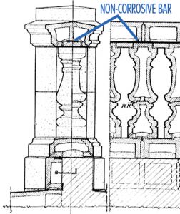
These are ornamental rails and copings supporting a series of balusters that can be single or multiple units. Balustrades were intended to act as monolithic elements with the function of the tensile bond capacity of the mortar, with mortar keys between units as the primary load resistance mechanisms (Figure 6). In some systems, these mechanisms are combined with metal bars extending through the units and across the top rail. As the mortar deteriorates and the embedded metal corrodes, the balustrades experience distress, including displacements, cracking, and bowing. For most balustrades, as long as vertical bars are installed in the balusters and the bars stitching the top and bottom rails are generally in good condition, the “unreinforced” balustrades may experience deflections and displacements but may not require repair or reconstruction. Current codes typically treat balustrades as handrails or guardrails, and it is often assumed that meeting these loading criteria is required, resulting in significant repairs to “reinforce” the system. Current “code compliant” balustrade repairs have consisted of dismantling and reconstructing according to the principles for reinforced masonry, which is often inappropriate for the existing application and may result in unanticipated distress.
Instead, in-kind repairs can consist of dismantling the balustrade and reconstructing it with stainless steel threaded rods and re-establishing the tensile capacity of the mortar by installing new mortar at the full bed joint of the unit. This repair is analogous to a net that keeps elements from dislodging from the building, instead of significant reinforcing of the balustrade elements to meet the code prescribed loads.
Conclusion
The application of modern structural evaluation criteria and contemporary standards/codes to historic façade systems can often result in excessively conservative or unnecessary repairs. These examples illustrate many of the issues faced when completing rehabilitation work and highlight ways of successfully working within the structural provisions in the code.
Without further development of the regulatory system, the question remaining is how to bring an existing building up to “modern” codes and standards. The most significant issue stems from the question: “Does a building necessarily have to meet modern structural provisions to provide for life safety?” Moreover, what does it mean if a building is not up-to-code? The need for sound engineering judgment, with an understanding of historic façade systems and basic structural behavior, is essential in the successful utilization, application, development, regulation, and modification of the structural rehabilitation codes.■