
The next edition of the Masonry Society’s TMS 402/602, Building Code Requirements and Specifications for Masonry Structures, is due to be published in 2022. Some of the anticipated changes are reviewed in this article, including some things that designers can use now. One of the most significant changes is not a technical change but a change in the length of the code cycle. The Masonry Society board approved a trial six-year cycle for updating the code in response to feedback from practicing engineers who are being overwhelmed by the constantly changing codes. The six-year cycle also enabled the committee to tackle larger issues.
Veneer Design
One of the most significant changes is a complete rewrite of the veneer chapter. This included extensive reorganization, simplifying the prescriptive design provisions, developing an engineered design method, and designing tables for fasteners for adhered veneer systems. This article covers two of the changes, and these changes can be used now.
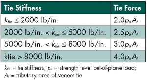
A simplified engineered design method was developed to determine the load on a veneer tie. The load is a factor multiplied by the tributary area of the veneer tie, with the factor based only on the veneer tie stiffness. The requirements are given in Table 1. Until standardized test data becomes available for ties, the Chapter also includes deemed-to-comply values, as shown in Table 2.
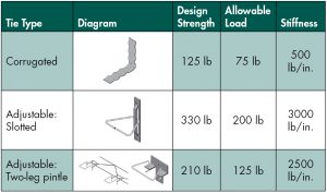
Consider a 20-foot-high building in an area with a basic wind speed of 105 mph, Exposure Category C, Risk Category II, and an elevation of 1000 feet. The components and cladding design wind pressure would be 32.7 psf. Based on prescriptive design, the maximum tie spacing would be 24 inches, and the maximum tributary area would be 2.67 square feet. A tie spacing of 16 inches x 24 inches would result in a tributary area of 2.67 square feet and meet the prescriptive requirements. Use the engineered design method with slotted ties and try a tributary area of 4 square feet or 24- x 24-inch tie spacing. The stiffness of a slotted tie is 3000 pound/inch, so the design force is 2.5puAt = 2.5(32.7psf)(4ft2) = 327 pounds. This is less than the design strength of 330 pounds, so a 24- x 24-inch tie spacing could be used. Since this method meets the alternative design provisions of TMS 402-16 Section 12.2.1, this design could be used now.
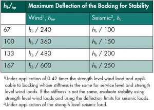
Another change to veneer design that can be used now is related to the out-of-plane stability of a backing. TMS 402-16 has the requirement, in the alternative design provisions, that the out-of-plane deflection of the backing shall be limited to maintain veneer stability. A maximum deflection for different backing height-to-thickness ratios (hb/tsp) provides an easy means to verify out-of-plane stability. The method was developed assuming a rigid veneer and a single mid-height crack, both conservative assumptions. The limiting ratios are given in Table 3. For the above example, with a height of 20 feet and a brick thickness of 3 5⁄8 inches, hb/tsp = 66.2. Thus, a backing with a deflection under service level wind loads of anything less than hb/240 = 1.0 inch is acceptable for stability. The backing stiffness would also need to be sufficient to limit a crack width, and typically a stiffer backing than hb/240 would be used to control crack width. It is important to note that hb is the height of the backing and not the height of the veneer. If there were two 10-foot stories in the example, the value of hb would be 10 feet.
Reinforcement Harmonization
TMS 402-16 had different provisions for the maximum size and percentage of reinforcement depending on whether the design method was allowable stress or strength design. The requirements have been harmonized and simplified. The proposed provisions are:
- Maximum bar size is #11
- Nominal bar diameter size cannot exceed one-eighth the least nominal wall thickness dimension (inches)
- Bar diameter cannot exceed one-third the least dimension of the gross grout space
- Maximum reinforcement percentage is 4% of the gross grout space, with 8% allowed at laps
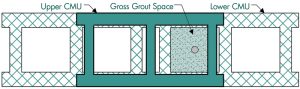
The gross grout space is defined as the area or dimensions available within the continuous grouted cell, core, bond beam course, or collar joint, considering the effect of unit offset in adjacent courses but neglecting possible mortar protrusions and the presence of perpendicular reinforcement, if any. The gross grout space is shown in Figure 1 for flanged units laid in a one-half running bond.
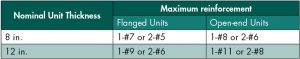
For designer convenience, tables are provided for maximum reinforcement for common configurations. Table 4 is a partial example of the tables.
Tension- and Compression-Controlled Sections
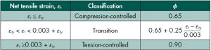
A major change was made in strength design provisions, with the introduction of compression-controlled sections. In TMS 402-16, there were only tension-controlled sections (ϕ = 0.9 for all cases of moment and axial load) and rather stringent limits on the maximum reinforcement. There were several issues with this approach, including that it was possible to have values on the interaction diagram above the balance point, even with the maximum reinforcement provisions. On the other hand, the maximum reinforcement provisions could be quite stringent in other cases, with #5 bars spaced at 8 inches in an 8-inch concrete masonry wall exceeding the maximum reinforcement limits under out-of-plane load, even with no axial load. The strength-reduction factor is determined from Table 5. The value of εty is determined as fy/Es, with fy being the yield strength of the reinforcement and Es being the modulus of elasticity of steel. This approach is similar to that used in the American Concrete Institute’s ACI 318, Building Code Requirements for Structural Concrete and Commentary.
With the adoption of compression-controlled sections, the maximum reinforcement restrictions were removed, except for intermediate and special reinforced masonry shear walls under in-plane loads and for beams. No change was made in the maximum reinforcement requirements for intermediate and special reinforced shear walls, as the maximum reinforcement provisions are needed to ensure there is adequate ductility in the walls. Maximum reinforcement provisions were kept for beams to ensure a ductile failure mode.
Figure 2 shows the interaction diagram for a 12-foot-high 8-inch concrete masonry wall with Grade 60 #5 @ 8 inches under out-of-plane loads. As mentioned previously, with TMS 402-16, the maximum reinforcement requirements can only be met if there is tension in the wall. Although there is a small region of flexure and axial load combinations allowed with TMS 402-16 that would not be allowed with TMS 402-22, the compression-controlled provision in TMS 402-22 allows significantly higher axial loads.
Net Shear Area
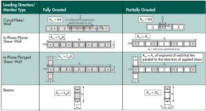
The net shear area, Anv, which is used to determine the shear strength of masonry members, has not been well defined and has caused confusion for designers. Figure 3 has been added to clarify the net shear area for reinforced masonry members. As shown, partially grouted beams are now allowed for masonry beams that do not require shear reinforcement. If shear reinforcement is required, the code mandates full grouting of the beam. Feedback from designers on the figure has been overwhelmingly positive.
Other Changes
Other revisions include changing the anchor bolt tension and shear strength provisions to be based on the ultimate strength of the anchor and not the yield strength. This provides consistency with anchor strength between TMS 402, ACI 318, and the American Institute of Steel Construction’s AISC 360, Specification for Structural Steel Buildings. Provisions were added for the use of deformed wire reinforcement. The smaller size of deformed wire reinforcement can be advantageous in some situations, such as when shear reinforcement is required in masonry beams. Prestressed masonry provisions had been limited to just walls. Provisions were added for prestressed masonry beams. Appendix A on empirical design was deleted. Appendix B on infills was moved to the main code and retitled as Chapter 12.
Summary
In summary, there are both technical changes and changes made to help designers in the 2022 edition of TMS 402. At the time of this article, the TMS 402/602 Code Committee is responding to comments from the Technical Activities Committee. The draft document will soon be available for public comment, with the anticipated public comment period being June 1 to July 15, 2021. Visit the Masonry Society website, www.masonrysociety.org, for additional information, to review the public comment version, and to submit comments. The committee has scheduled about 9 months to review and respond to public comments. The anticipated publication date of the next version of TMS 402/602 is October 2022, which will be in time for the hearings for the 2024 edition of the International Building Code.■