
Part 1
The ability to premanufacture elements helped to proliferate concrete as an essential building material. Rectangular blocks, for example, could be manufactured rapidly and easily transported to make many types of structures, from steps, sheds, and buildings to intricate tunnels, aqueduct systems, and bridges. These emerging technologies and the infrastructure they enabled have continually reshaped the way communities are organized through more efficient transportation of people and goods. The next step in the evolution of precasting concrete is prestressed concrete. This article discusses some of the technologies and materials that make modern prestressing techniques achievable.
Prestressing Techniques
Precast prestressed girders are a type of concrete girder that facilitates the rapid construction of a bridge using girders fabricated off-site and then transported and erected into place at the job site. Because these girders require little to no falsework, they are a preferred solution for jobs where construction speed or minimal traffic disruption is required. Prestressed girders are particularly economical when longer beam lengths are required; some types are suitable for spans of up to 200 feet.
Prestressing the concrete reduces the size of the required cross-section and the depth of the beam. The smaller cross-section size reduces the self-weight of the beam by requiring less concrete. Prestressing members allows for a lower span-to-depth ratio, which allows for longer spans. The presence of mild steel and high-stress tensioning tendons, when properly designed, minimizes cracking and increases the member’s durability.
Post-Tensioned Elements
Post-tensioning is the method of bundling a group of reinforced concrete elements together, after they have been cast and installed in their final location, to create enough lateral compression that the beam-unit will resist the desired amount of vertical loading. This is perhaps the most readily available method of prestressing objects. This method requires that the beam elements are cast with hollow tubes such that prestressing tendons can be installed and loaded in situ.
Pretensioned Elements
Pretensioning is the method of introducing high-strength steel tendons to the beam element, stressing them to a predetermined load, and then casting the concrete around them. Once the concrete has gained enough strength, the load is released from the steel tendons, thereby transferring this load to the concrete portion of the composite member. It is the relative loading of the strands before the concrete is cast that gives this method its name. Pretensioned beam elements are the main focus of this article.
Design of Prestressed Girders
The introduction of high-stress strands into the tension fibers of a concrete member allows for dramatic increases in the member’s functionality. However, the same strands that make this increase possible have characteristics that need to be designed and monitored correctly. The concrete-steel interaction moves from a juxtaposed partnership to a synergistic relationship. Prestressing strands stimulate the compressive resistance of concrete long before putting the member into service, an action that continues to intensify unless mitigated by other design considerations. Engineers have continued to develop design methodologies that harness the power of prestressing while mitigating the less desirable effects of the inherent material tendencies involved. The result is a design process that leverages prestressing benefits and allows for high serviceability for the entire design life.
Steel Elements
Mild steel reinforcement is most commonly specified to be 60 kips per square inch (ksi). This is typical of non-prestressed concrete members, and the material itself does not change for prestressed applications.
Standard prestressing steel has a 270 ksi ultimate tensile strength. This steel is used in strands, a group of wires wound helically, or as a tendon, which can describe a single wire, a strand, or a group of strands used together. Design stresses in this steel are limited by the American Concrete Institute (ACI) and the American Association of State Highway Transportation Officials (AASHTO) specifications during jacking, immediately after prestress transfer, at anchorage devices and couplers, and at service limit states. The primary characteristics of prestressing steel that must be considered during design are the stress-strain curve and relaxation of the prestressing strands. These are behavioral characteristics of the prestressing steel that directly correlate to the overall results of the prestressing process.
High Strength Concrete
High strength concrete (HSC) is concrete that has 28-day compressive strengths of 10 ksi or more. The use of HSC, rather than normal-strength concrete, enables a section of a given size to support larger loads or span longer distances. The improved durability usually associated with HSC increases the lifespan of structures and increases the ability to meet greater future loading demands.
High-strength concrete has a higher paste content, but the paste has a lower water/cement ratio. As a result, the shrinkage of high-strength concrete is about the same as that of normal concrete.
Prestressed Concrete Design Considerations
The instantaneous and time-dependent implications of the effects of prestressing steel must be understood and accounted for in the prestressed concrete girder design process.
Loss of prestress can be characterized as that due to instantaneous loss and time-dependent loss. Losses due to anchorage set, friction, and elastic shortening are instantaneous. Losses due to creep, shrinkage, and relaxation are time-dependent. For pretensioned members, prestress loss is due to elastic shortening, creep of concrete, and steel relaxation.
Elastic shortening is the immediate shortening of the concrete member due to the application of prestressing. Prestressing strands are initially tensioned with hydraulic jacks at solid abutments, which causes them to stretch slightly. Concrete is then cast around the tightened strands to form the beam element. Once the concrete has cured sufficiently, the initial prestress is released, which effectively loads the concrete member with the remaining stress within the strands as they try to return to their original length. The result is that the concrete encounters enough stress to buckle slightly and deform longitudinally, resulting in a slightly shorter member than what was cast. As the member shortens, the strands shorten also. Because of this shortening, the strands lose a portion of their internal stress.
Shrinkage loss is associated with the time-dependent change in length of concrete along the direction of the tendons. As concrete shrinks over time, the stands themselves also shrink, causing a reduction of the effectiveness the prestressing strands provide to the member. Similar to the effect of elastic shortening, shrinkage loss occurs because the prestressing strands are anchored into the concrete itself and must react, i.e., shorten, as the concrete does.
Creep is the stress-dependent change in length of a girder subjected to compression along the direction of the tendons.
Relaxation is the stress-dependent gradual decrease of the prestress force over time. The strands have a slightly lower modulus of elasticity. Prestressing steel encounters more deformation than reinforcing steel when loaded but has a substantially higher ultimate strength. This deformation under loading is commonly referred to as relaxation. Relaxation in steel strands is much akin to the reduction of size in concrete members due to creep. The amount of relaxation a strand encounters is dependent on the amount of initial stress in the strands relative to the ultimate stress.
The combination of elastic shortening, shrinkage, creep, and relaxation results in a cumulative deformation on the concrete member and a mitigating factor in the prestressing strand’s efficacy that must be accounted for in the design. The interaction of elastic shortening, shrinkage loss, and creep regarding total prestressing loss can be summarized as follows: bridge girders instantaneously shrink, or shorten, under the axial load applied by the prestressing tendons. All concrete shrinks as internal humidity reduces, and this phenomenon also begins immediately. Additional instantaneous shortening occurs from the application of the various dead loads (e.g., bridge deck, parapet walls). On a strain-time curve, a member’s flexural loading would be evident by the presence of a jump in strain at the time of loading. Because the dead loads are sustained, the beam continues to deform over time. All three of these phenomena cause the entire member to shrink, effectively reducing the stress within the prestressing strands by 25,000 to 50,000 psi in some cases.
Accurate estimation of the total prestress loss requires recognition that the time-dependent losses resulting from creep and relaxation are interdependent. If required, rigorous calculation of the prestress losses should be made following a method supported by research data. However, for conventional construction, such refinement is seldom warranted or even possible at the design stage, since many of the factors are either unknown or beyond the designer’s control.
Raja (2012) notes that the increased modulus of elasticity reduces the elastic shortening due to the prestress force. Further, the long-term deflection due to creep and shrinkage are also reduced. Hence, by using high strength concrete, the prestress losses are significantly reduced, increasing the efficiency of such construction.
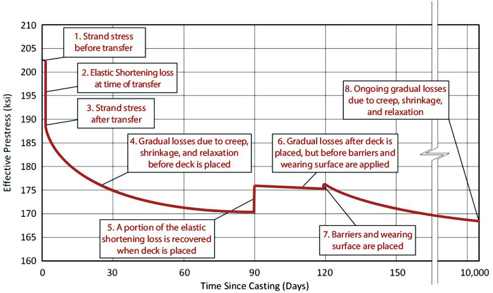
Figure of prestress loss over time (Source: MDOT 2019).
AASHTO’s Load and Resistance Factor Design (LRFD) Article 5.9.5.3, based on the National Cooperative Highway Research Program (NCHRP) Report 496, considers the interaction of creep and shrinkage throughout the life of the member. This method breaks up the evaluation of prestressing losses into three distinct periods: 1) at transfer, 2) transfer to bridge deck placement, and 3) bridge deck placement to final time. The first period accounts only for the instantaneous effects of elastic shortening when the stress in the strands are transferred to the concrete member and is illustrated by the near-vertical curve between Points 1 and 3 in the Figure. The remaining periods include the long-term effects of shrinkage, creep, and relaxation within the girder. The parabolic curves illustrate time-dependent losses in the Figure. However, the third period adds the effect of differential shrinkage associated with the addition of a composite deck section. Deck-only and full-section continuity are discussed in the second part of this article in a future issue.
AASHTO uses several assumptions to simplify the prestressing loss calculations. This method assumes 1) normal weight concrete that was steam or moist-cured, 2) low-relaxation strands, and 3) average exposure conditions and temperatures. AASHTO 4 also has provisions for use with lightweight concrete.
This is the first of two articles providing a high-level overview of the design considerations of prestressed concrete girders. In Part 2, the discussion continues with fundamental design considerations for internal stress distributions within prestressed concrete girders and the methodology for applying those principles.■
References
Caltrans. Bridge Design Practice Guide Chapter 8: Precast Pretensioned Concrete Girders, California Department of Transportation, Sacramento, CA, 2015.
Hawkins, N. and Kuchma, D. NCHRP Report 579: Application of LRFD Bridge Design Specifications to High-Strength Concrete: Shear Provisions, Transportation Research Board, Washington D.C., 2007.
Raja, N. Thesis: Design of Prestressed Concrete Girder Bridge, Edith Cowan University, Perth, Western Australia, 2012.
Wassef, W.G., Smith, C., Clancy, C., and Smith, M. Comprehensive Design Example for Prestressed Concrete (PSC) Girder Superstructure Bridge with Commentary, Modeski and Masters, Inc./Federal Highway Administration task order DTFH61-02-T-63032, Arlington, VA, 2003.
Wight, J. Reinforced Concrete Mechanics and Design, 7th Ed., Pearson, Hoboken, NJ, 2016.
WisDOT. WisDOT Bridge Manual Chapter 19 – Prestressed Concrete, Wisconsin Department of Transportation, Madison, WI, 2019.