
Reconciling the 2018 IBC, ACI 318-19, and PCI’s 2019 Report
This is a follow-up to a previous STRUCTURE magazine article titled Rethinking Seismic Ductility (March, 2016). The previous article presented possible shortcomings associated with the International Building Code (IBC) prescriptive seismic design philosophy used for both auger cast piles and prestressed piles to contrast foundation ductility design with that used for other structural elements. It also provided a side-by-side comparison of design and performance issues associated with auger cast piles and prestressed piles.
Recently, there have been significant changes to the seismic design provisions for prestressed piles. Previous versions of the American Concrete Institute’s ACI 318, Building Code Requirements for Structural Concrete and Commentary, did not address the seismic design of prestressed piles. Now, both ACI 318-19 and the 2018 IBC include matching seismic design criteria for prestressed piles. It is understood that these seismic provisions will be excluded from future editions of the IBC now that they fall under the purview of ACI 318.
As to specific provisions, new confinement equations based on research performed at Iowa State University (ISU) are included in both ACI 318-19 and the 2018 IBC. These equations replace those used since the 2000 IBC, which were based on expected ductility performance that was not wholly quantified in the literature at the time. The ISU research recommends the newly adopted confinement equations with a presentation of results of a comprehensive study of confinement requirements for square and octagonal solid piles with circular spiral confinement and 2 inches of cover to the spiral. Square piles with square confinement were not included in the scope of the research. Overall, the authors agree that the adoption of the new equations was an excellent addition to both ACI 318-19 and the 2018 IBC since the resulting quantity of confinement spiral is now based on specified curvature ductility capacities at locations of pile hinging (i.e., 18 for areas of high seismicity and 12 for areas of moderate seismicity). Another encouraging result is that the new equations yield a required spiral quantity very similar to what was required by previous versions of the IBC. In other words, the overall cost of prestressed piles changes very little with the adoption of the new equations. The code committees adopting the equations also recognized that piles that are significantly stronger than required to resist seismic demands might not need seismic confinement. They provided an exception for piles that have been designed using seismic overstrength factors. The only drawback of adopting new confinement equations is that the ISU researchers were not satisfied with the amount of moment drop that occurred at a plastic hinge after the onset of cover spalling. To address their concerns, ISU researchers proposed axial load limits as an attempt to provide what they considered to be a more reliable seismic response.
2018 IBC and ACI 318-19
The 2018 IBC and ACI 318-19 prestressed pile provisions present factored axial load limits for piles. For Seismic Design Categories C through F, IBC 1810.3.8.3.4 and ACI 18.13.5.10.6 limit the factored axial load for all square piles to 0.2f´cAg. In many cases, this limit is less than the factored axial loads traditionally considered for the design of commonly used 14-inch square piles in areas of high seismicity. As discussed above, the code committees established the new axial load limit when adopting the new confinement equations. ISU researchers proposed an axial load limit of 0.2f´cAg for 14-inch square piles with circular strand configurations and circular spiral with 2 inches of clear cover. Square piles with square confinement were not considered in these recent studies.
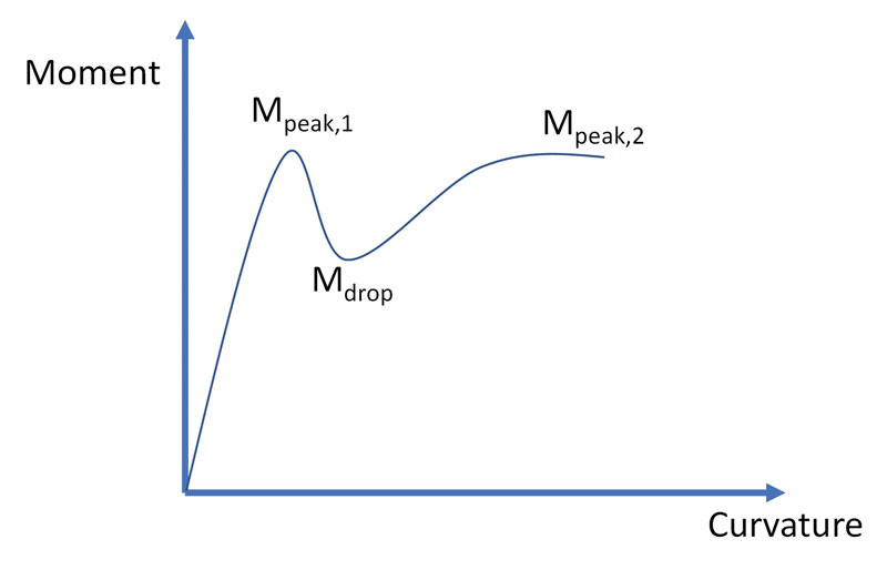
Figure 1. Critical moments developed during moment-curvature
analysis of prestressed concrete piles.
The basis of the limit on axial load described above can be explained using Figure 1. A drop in moment capacity to a level Mdrop after the first peak moment Mpeak,1 and subsequent to reaching the second peak moment Mpeak,2 is evident. The previous research showed that the percent moment drop is related to the axial load applied during moment-curvature analysis. The ISU research suggested that the drop should be limited to approximately 40% of the first peak moment and that the most effective way of adhering to the 40% limit was to limit the axial load. Therefore, axial load limits were recommended for all 14-inch pile configurations to prevent loss in moment relative to the first peak moment in excess of approximately 40%, based on pile configurations considered (i.e., 14-inch square piles with 2 inches cover and round spiral). The drop in moment reportedly correlated well with another desired performance outcome; maintaining a response in which the curvature at the initiation of tension cracking (φcr) is less than the curvature associated with the initiation of unconfined concrete spalling (φsp), where strain in the outermost unconfined compression fiber equal to 0.004 is taken as the value that spalling would initiate.
To the best of the authors’ knowledge, it does not appear as though recent studies have attempted to define or study the rationale for the concern or to determine if the moment drop would actually result in poor performance of the subject piling. Instead, the authors note that larger moment drops were deemed to be “unacceptable for piles in seismic regions” and “the stability of the pile experiencing significant moment drop may not be dependable.”
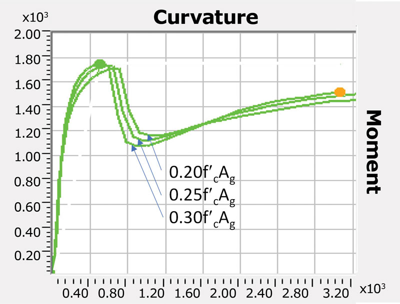
Figure 2. Typical moment (k-in.) vs. curvature (in.-1) plots for a commonly used 14-inch prestressed pile.
As shown in Figure 2, results from an ongoing Citadel research project on pile ductility suggest that, in many cases, increasing the axial load limit from 0.2f´cAg to 0.3f´cAg has a negligible impact on expected seismic performance. Note that moment-curvature stability is unaffected in Figure 2, and the area under the moment-curvature curve is approximately the same for all three axial load variations shown.
2019 PCI Report
The Precast/Prestressed Concrete Institute’s 2019 PCI Report, Recommended Practice for Design, Manufacture, and Installation of Prestressed Concrete Piling, presents both prescriptive and performance-based design procedures for prestressed piles. The prescriptive procedure is similar to the current procedure presented in the 2018 IBC and ACI 318-19. The performance-based design option is similar to procedures for the seismic design of piles contained in American Society of Civil Engineer’s ASCE/COPRI 61-14, Seismic Design of Piers and Wharfs, Caltrans Seismic Design Criteria (2019) for bridges, and ASCE/SEI 41-17, Seismic Evaluation and Retrofit of Existing Buildings. Procedures for prescriptive and performance-based design are presented separately for piles considered part of the lateral force-resisting system (i.e., bridges and piers) and for piles that are not considered part of the lateral force-resisting system (i.e., buildings). Note that building piles are typically designed to remain elastic during the design earthquake event. Buildings are required to be detailed such that seismic damage is ductile and occurring above the foundation level. The damage that occurs in the lateral force-resisting system above grade dramatically reduces the maximum force delivered to piles. Although performance-based design of bridge and pier piling is commonplace in the industry, performance-based design of building piles is exceptionally complicated and not commonly used in practice. When performance-based design is used to design building piles, more economical pile designs are possible. Prescriptive requirements related to spiral quantity, spiral placement, connection detailing, splice detailing, and other design issues are directly modeled to accurately predict, rather than just assume, their performance.
Designing for Axial Loads
How can an engineer design prestressed piles for a load above the axial load limit and still meet the code’s intent?
The authors’ opinion is that engineers who wish to design for axial loads in excess of the prescribed limits, while complying with the current axial load limits now established by the 2018 IBC and ACI 318-19, have three Options. Options 1 and 2 below assume that a drop from the ultimate moment in excess of 40% is problematic, as opined by the Iowa State University researchers. Option 3 may provide a more practical approach, but it is not currently available. Current PCI research underway at The Citadel will result in conclusions and practical applications for Option 3 by the end of 2020 or early 2021.
Option 1
The easiest solution to the axial load limit is to perform a moment-curvature analysis of the concrete pile cross-section in question and verify that the moment drop from the ultimate moment is less than or equal to 40%. It is likely that many actual conditions (e.g., cover, axial load, and spiral configurations) do not violate the ISU researchers’ concern regarding moment drop, and the new confinement equation is appropriate for use at loads higher than the axial load limit. Valid moment-curvature analytical models must account for confined and unconfined concrete and include nonlinear material properties. The required analysis can be performed using readily available commercial software programs such as SAP2000. The designer should note that Option 1 may be considered by some as an application of the Alternate Means and Methods provisions allowed by the governing codes and standards and used by engineers to satisfy the intent of the code when a particular provision is inappropriate or really doesn’t apply. As such, some jurisdictions may require notification when using this approach.
Option 2
In accordance with procedures defined in the 2019 PCI Recommended Practice for Design, Manufacture, and Installation of Prestressed Concrete Piling, designers can design the piles using performance-based design. Performance-based design procedures ensure adequate confinement is placed along the length of the pile by providing a spiral that results in plastic rotation capacities exceeding plastic rotation demands. Performance-based design procedures account for moment loss directly.
Option 3
The Citadel is currently working on a research project to more closely examine and possibly modify the axial load limits proposed by ISU researchers. The Citadel project considers circular and square spiral with different covers and strand configurations used in practice. The study aims to determine if a more accurate axial load limit can be established and justified by the results. The extent to which the moment strength recovers throughout the moment-curvature response, indicated as Mpeak,2 in Figure 1, is examined as a more significant contributing factor in the pile’s overall stability. This was not a consideration of the previous study.
Conclusion
As a final note, the authors’ goal for this article is to help establish a consistent methodology for the design of different types of piles and provide structural engineers of record with tools that result in safe designs that are not unnecessarily costly. Currently, and as noted above, Options 1 and 2 represent the peer-reviewed and codified options available to the pile designer. However, inconsistency in the design requirements for auger cast piles versus prestressed piles is interesting and should be brought to the reader’s attention.
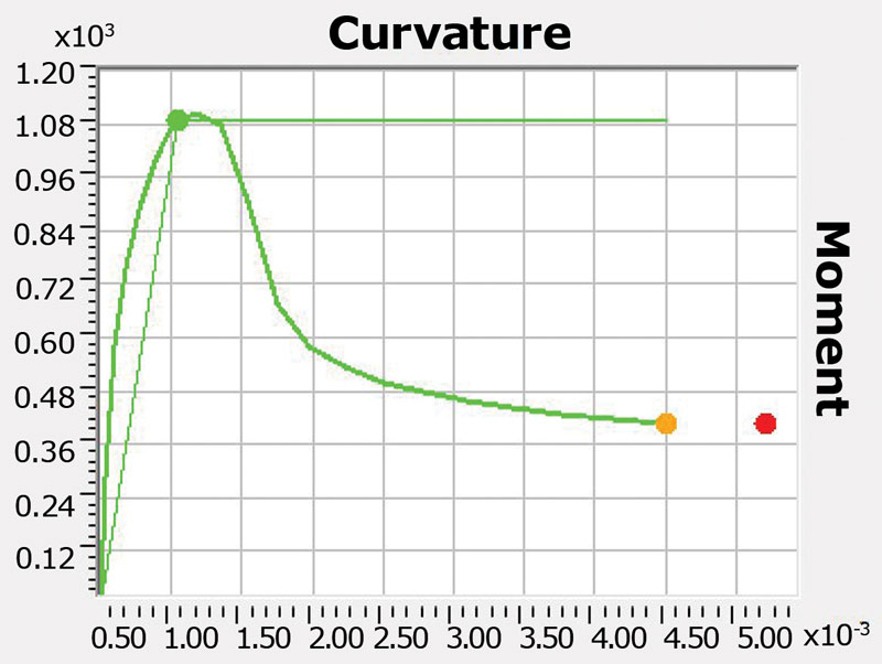
Figure 3. Moment-curvature for 14-inch auger cast pile with 0.20f´cAg axial load. Note drop greater than 40% and no return to Mpeak,2.
Figure 3 provides the moment-curvature response of a 14-inch auger-cast pile with prescriptive confinement reinforcing. It can be seen that a similarly sized auger-cast pile can be shown to be more susceptible to the moment drop issue without the benefit of a second peak moment. Therefore, applying a consistent methodology would disallow the use of the represented 14-inch auger-cast pile with code allowed minimum reinforcement.
Acknowledgments
The authors wish to thank the Precast/Prestressed Concrete Institute (PCI) for their support. The Citadel research discussed in this article would not be possible without the financial support from PCI and PCI committee members’ input.■
References
Fanous, A., S. Sritharan, M. Suleiman, J. Huang, and K. Arulmoli. 2010. Minimum Spiral Reinforcement Requirements and Lateral Displacement Limits for Prestressed Concrete Piles in High Seismic Regions. Final report to PCI. ISU-ERI-Ames Report ERIERI-10321, Department of Civil, Construction, and Environmental Engineering, Iowa State University, Ames, IA.
AASHTO (2014). AASHTO LRFD Bridge Design Specifications, American Association of State Highway and Transportation Officials, Washington, D.C.
ACI 318 (2014). Building Code Requirements for Structural Concrete and Commentary, American Concrete Institute, Farmington Hills, MI.
ASCE/SEI 41-13, Seismic Evaluation and Retrofit of Existing Buildings, American Society of Civil Engineers, Reston, VA.
ASCE/SEI 7-10, Minimum Design Loads for Buildings and Other Structures, American Society of Civil Engineers, Reston, VA.
ASCE/COPRI 61-14, Seismic Design of Piers and Wharfs, American Society of Civil Engineers, Reston, VA.
IBC (2018). International Building Code, International Code Council, Washington, D.C.
MOTEMS (2016). 2016 CCR, Title 24, Part 2 California Building Code, Chapter 31F Marine Oil Terminals, International Code Council, Washington, D.C.
SAP2000 (2018). Computers and Structures, Inc.