
Cross-Laminated Timber (CLT) panels are becoming increasingly common as a roof or floor deck system in mass timber buildings. The roof and floor deck systems need to be carefully engineered and detailed to serve as diaphragms resisting wind and seismic loads. The diaphragm transmits lateral loads to the vertical lateral load resisting elements – usually shear walls or braced frames.
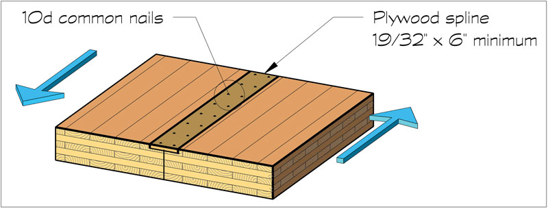
Figure 1. Longitudinal side joint.
It is common for CLT floor decks to have a concrete topping slab for sound isolation. The concrete topping slab can be detailed to serve as the lateral load resisting diaphragm, but it is often more practical to engineer the CLT deck to serve as the diaphragm. The American Wood Council’s (AWC) 2021 Special Design Provisions for Wind & Seismic (SDPWS), referenced in the 2021 International Building Code (IBC), contains CLT diaphragm design provisions.
Diaphragm Flexibility
In most instances, it is reasonable to consider CLT floor and roof decks to act as rigid diaphragms with lateral loads distributed to the vertical resisting elements based on their relative stiffness. It is recommended that the aspect ratio (L/W) of the rigid diaphragm not exceed 3:1 if there is a non-composite concrete topping (2½-inch minimum thickness) or 2:1 if there is no concrete topping. If the aspect ratio exceeds these limits but is not more than 4:1, the diaphragm may be modeled as semi-rigid.
Alternatively, rather than performing a semi-rigid diaphragm analysis, which can be tedious, the lateral analysis may be run twice – once assuming a rigid diaphragm and once assuming a flexible diaphragm, and designing for the envelope of the two. If the lateral force-resisting elements are similar in stiffness and well distributed throughout the footprint, the two solutions will often not be far apart.
The CLT decks can be considered flexible diaphragms only if calculations demonstrate that the diaphragm’s in-plane deflection is more than twice the average drift of the vertical resisting elements. This is outlined in the American Society of Civil Engineers’ ASCE/SEI 7-16, Minimum Design Loads and Associated Criteria for Buildings and Other Structures, Section 12.3.1.3. In no case should the diaphragm aspect ratio exceed 4:1.
Diaphragm Strength
CLT shear values are based on ANSI/APA PRG-320, Standard for Performance-Rated Cross-Laminated Timber. V (in-plane shear strength) = t (thickness of cross plies) × 12” × Fv × 1.6 (CD) / 1.5.
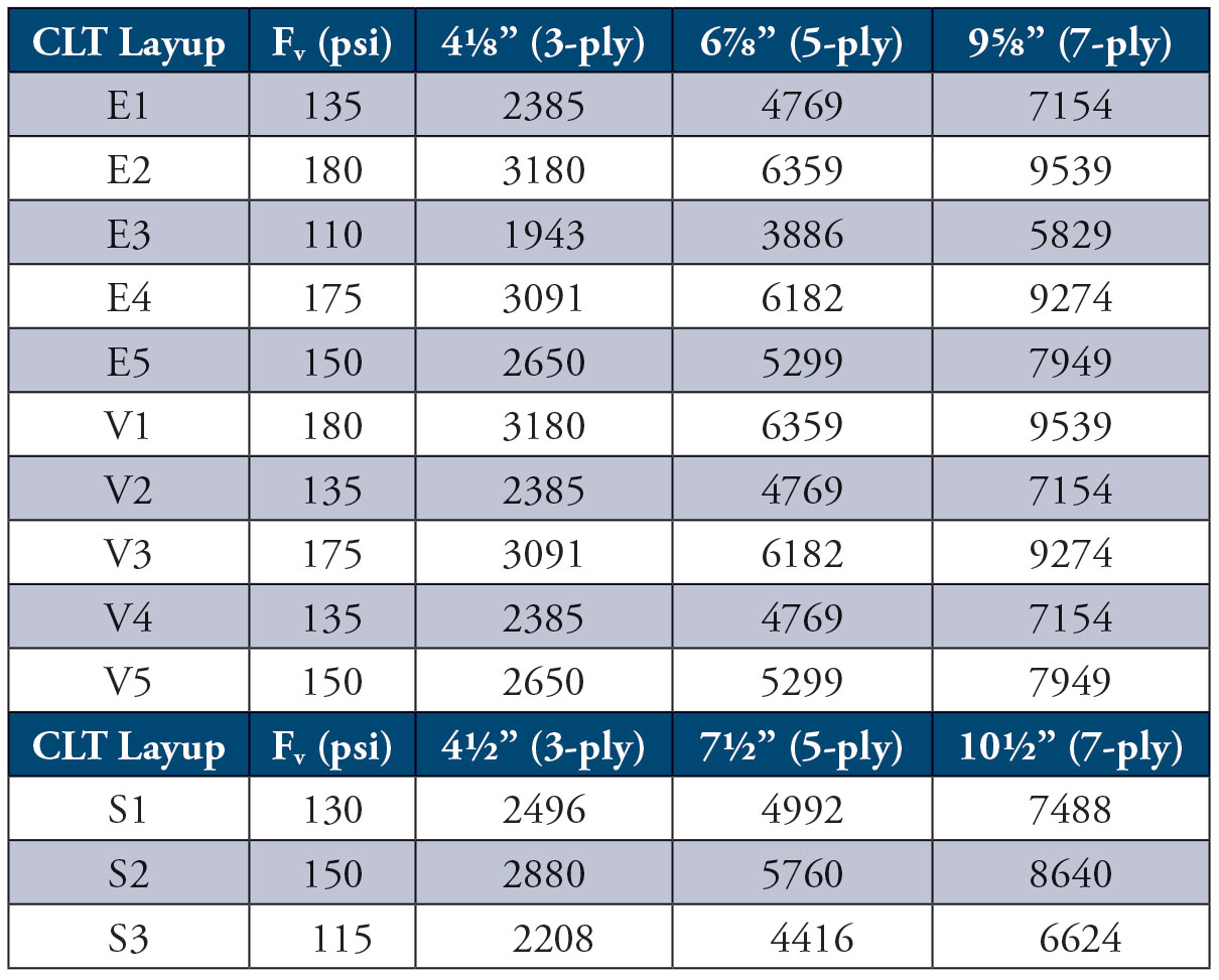
Table 1. CLT in-plane shear ASD reference design values (lbf/ft of width).
The in-plane shear strength of a CLT panel is controlled by the shear strength of the transverse cross laminations. The allowable in-plane shear values are shown in Table 1. Per 2021 SDPWS, CLT panels should be designed to resist 2.0 times the induced shear associated with seismic loads to preclude a non-ductile shear rupture.
The in-plane shear strength of a CLT deck is typically limited by the strength of connections between panels and connections at boundary elements rather than by the strength of the CLT panels. Consequently, careful detailing of the panel connections and fasteners is crucial.
CLT Connections
Longitudinal side joints between CLT panels are most commonly achieved with plywood splines fastened with common nails. Spline joints deform and dissipate energy during a seismic event, lending ductility to the diaphragm. If thicker splines are used or fastened with screws rather than common nails, some ductility is sacrificed. The allowable unit shear capacity for plywood splines are shown in Table 2.
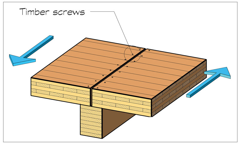
Figure 2. Transverse end joint.
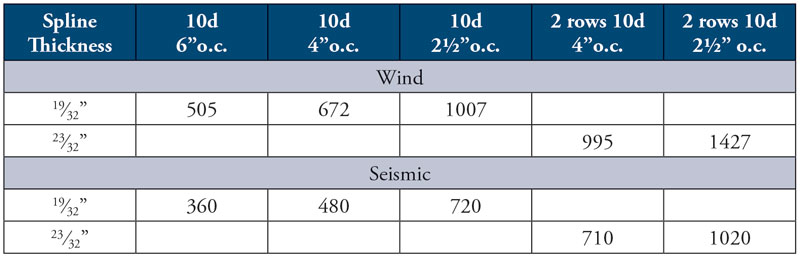
Table 2. Allowable unit shear capacity of splines (lbf/ft).
Some dynamic testing of spline joints with screw fasteners has been done at the University of British Columbia. The research suggests that spline joints with inclined screws loaded axially typically exhibit high initial stiffness and ultimate static capacity but are prone to non-ductile failure. Spline joints with screws installed at 90 degrees and loaded in shear exhibited lower initial stiffness and ultimate static capacity but failed in a more ductile fashion.
Transverse end joints between CLT panels must resist the same in-plane shear as the longitudinal joints. In most instances, the ends of the CLT panels are supported on a glulam timber beam, and the shear is transmitted through the beam with timber screws.
Diaphragm boundary elements (chords and collectors) are often glulam timber beams. Connections at the ends of timbers serving as boundary elements must be detailed to resist the axial forces induced into them to maintain the continuity of the chords. If the chord forces must be resisted by the CLT panels rather than by timber beams, steel straps are needed at the panel joints. Per 2021 SDPWS, chord splices should also be designed to resist 2.0 times the induced seismic chord force to preclude non-ductile behavior. The timber screws fastening the CLT panels to the boundary timbers need to be spaced to transmit the chord and collector forces.
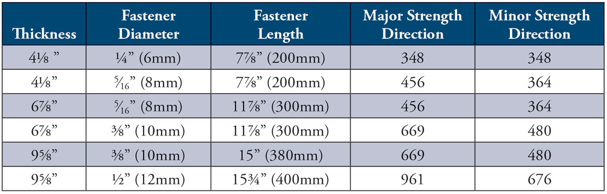
Table 3. Allowable shear capacity of timber screws in CLTs (lbf).
The allowable shear capacity of timber screws fastening CLT panels to timber beams is shown in Table 3. The values in Table 3 are based on timber screws with a minimum Fyb of 136.6 ksi, a CLT specific gravity of 0.42, and a timber beam specific gravity of 0.49. The load is assumed to be applied parallel to the grain of the timber beam. These values have been increased for a load duration factor, CD, of 1.6 and a diaphragm adjustment factor, Cdi, of 1.1
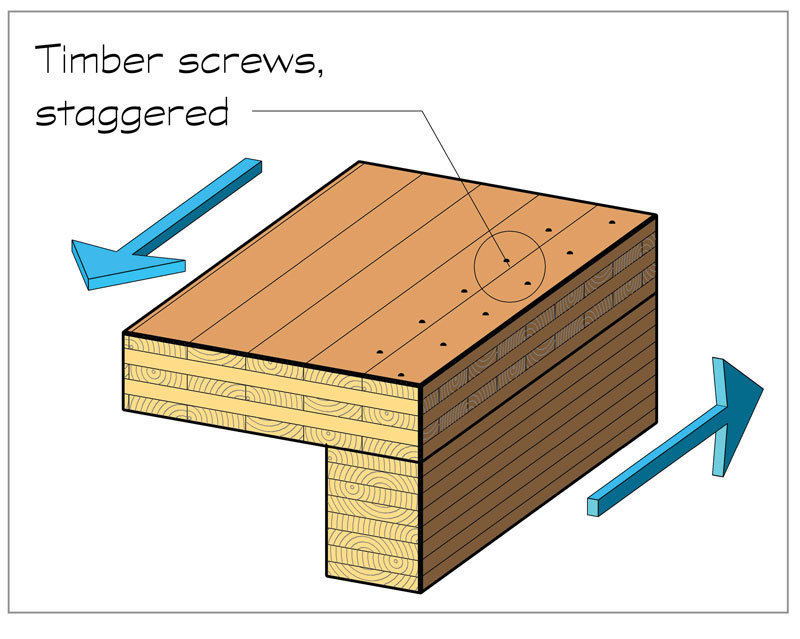
Figure 3. Diaphragm boundary.
The timber screw values contained in Table 3 are controlled by Mode IV fastener yielding in accordance with AWC’s National Design Specification® for Wood Construction 12.3.1 as required by 2021 SDPWS.
This article is reprinted, with permission, from the Timber Frame Engineering Council (TFEC) Timber Design Guide 2020-19. TFEC documents are available at www.timberframeengineeringcouncil.org.■