
Understand the Consequences of Specifying Them to Resist Horizontal and Vertical Loading
Most structural engineers would not dream of deliberately violating any building-code provisions, but some are doing it on a regular basis – unwittingly. The problem area is concrete slabs cast on the ground. These concrete elements are frequently designed to serve as vertical supports for posts and columns, lateral ties, lateral-load transfer devices, and lateral bracing for walls. There is nothing wrong with relying on concrete slabs for these needs – as long as they are designed as structural slabs, like those in elevated floors, rather than common slabs on ground (SOG) that are relatively thin, reinforced with welded-wire fabric (WWF), if that, and contain control and isolation joints. It is this type of slab that is problematic for structural uses.
Structural Slabs vs. SOG
Are all SOG considered structural elements? Generally, the answer is “no,” except as discussed below. The primary purpose of an SOG is to provide a dry, hard, and level surface. In most cases, the building structure does not behave differently if the ground floor is made of bituminous concrete, precast pavers, or even crushed stone. Structural slabs are, well, structural and perform a structural function besides supporting live loads and loads from equipment, racks, and the like. According to the American Concrete Institute’s ACI 318-19 Section 1.4.8:
This Code does not apply to design and construction of slabs-on-ground, unless the slab transmits vertical loads or lateral forces from other portions of the structure to the soil.
The International Building Code (IBC) contains a similar statement. Put differently, ACI 318-19 Section 13.2.4, Slabs-on-Ground, states:
Slabs-on-ground that transmit vertical loads or lateral forces from other parts of the structure to the ground shall be designed and detailed in accordance with applicable provisions of this Code. Slabs-on-ground that transmit lateral forces as part of the seismic-force-resisting system shall be designed in accordance with 18.13 [seismic provisions].
It is quite clear: The concrete slabs that directly support vertical structural elements (e.g., columns or walls) or are involved in lateral load transfer must be designed as structural elements subject to ACI 318 provisions for structural concrete. The engineers who miss this critical point do so at their own risk.
Designing SOG for Structural Loads
Is there a way to avoid designing such concrete slabs as structural concrete elements? After all, ACI 318 references another document, ACI 360R-10, Guide to Design of Slabs-On-Ground. (To avoid confusion on grammar, ACI chooses to hyphenate the term “slabs-on-ground,” but the IBC and the author do not.)
ACI 360R includes a wealth of information on various SOG types, their joints, loads, etc. Yet, there is no escape from complying with structural provisions of ACI 318 for the concrete slab involved in load transfer (see ACI 360R Sections 3.2.4 and 12.1). The latter provides some examples of concrete slabs that must be designed as structural members per ACI 318. These include the slabs supporting vertical loads from columns, posts, and load-bearing walls, as well as the slabs helping resist lateral loads from perimeter foundation walls and pre-engineered metal building columns. Note that, in all these cases, the slabs are subjected to tensile or flexural loading, as opposed to compression or bearing, which could have been resisted by some concrete alternatives such as pavers.
The slab designed for tension or flexure must be properly reinforced. As the ACI 318-19 Commentary Section R14.1.3 explains, the use of structural plain concrete should be limited to members primarily in compression. Therefore, when the slab resists tension or bending, in most cases it should be designed as a one-way (and sometimes two-way) structural slab. For the sake of simplicity, consider the code provisions for one-way structural slabs, such as those found in elevated concrete floors and roofs. The attributes of a properly designed structural slab are:
- An appropriate combination of thickness and primary flexural reinforcement to meet the specified strength and serviceability criteria.
- A minimum amount of reinforcement to resist the effects of temperature changes and concrete shrinkage.
- Structural integrity reinforcement (the new provisions added in ACI 318-19).
More can be learned by examining how these structural provisions would work in SOG.
Minimum Slab Reinforcement
For one-way non-prestressed slabs, the minimum areas of flexural reinforcement and the reinforcement required to resist the effects of temperature changes and shrinkage are the same (compare ACI 318-19 Sections 7.6.1 and 24.4.3). In both cases, the minimum bar areas are equal to 0.0018 times the slab’s gross area, but the maximum spacing of the bars differs. There are also new provisions for integrity reinforcement. Thus, there are three relevant issues:
- According to ACI 318-19 Section 7.7.2.3, the maximum spacing of primary flexural reinforcement is equal to the lesser of three times the slab thickness and 18 inches. Still, the spacing is much smaller in most cases. Following Section 24.3.2, the maximum spacing is 12 inches or less (see sidebar at end of article).
- By contrast, the spacing of deformed reinforcement to resist shrinkage and temperature effects is limited to the lesser of five times the slab thickness and 18 inches. Unlike primary flexural reinforcement, which is placed near the tension surface, shrinkage and temperature reinforcement may be placed anywhere in the slab in one or two layers. The Commentary Section R24.4.3.4 states that splices and anchorage of this reinforcement must develop its specified yield strength.
- ACI 318-19 adds a new Section 7.7.7, which calls for structural integrity reinforcement in cast-in-place one-way slabs. At least one-quarter of the maximum positive-moment reinforcement should continuously extend from one end of the slab to the other. This reinforcement should be anchored at the end supports to develop the bars’ yield strength, and it should use Class B tension lap splices or mechanical or welded splices.

Figure 1. Slab on grade with reinforcing bars.
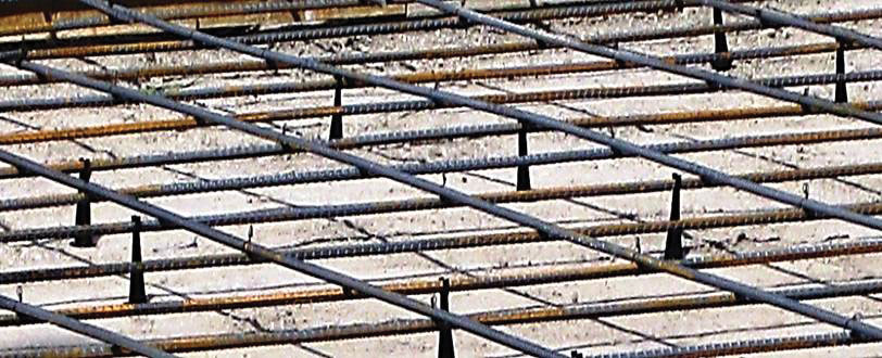
This discussion clarifies that all three types of bars envisioned in ACI 318 consist of deformed reinforcement (Figure 1). It might be possible to use its lightweight prefabricated version – deformed WWF mats – but not the plain WWF common in SOG, since bond on smooth steel is not recognized by ACI 318.
Also, the common WWF used in SOG has an insufficient area for structural purposes. For example, using the minimum reinforcing ratio of 0.0018, the cross-sectional area of the ubiquitous 6×6-W2.9xW2.9 WWF (0.058 in2/ft) is not even sufficient for a 3-inch-thick slab. Instead, to comply with ACI minimum reinforcing ratio and bar spacing requirements, slabs from 4 to 7 inches thick should have at least #4 bars at 12 inches on centers; closer spacing or larger bar sizes are needed for thicker slabs.
Sawcut Joints
A typical SOG includes three different types of joints, described in detail in ACI 360R Chapter 5. These are:
- Construction joints, which define the extent of concrete placed at one time. In SOG, these joints often have greased dowels that permit in-plane movement but resist vertical offset. In structural slabs, reinforcement typically continues through the joints.
- Isolation joints, which isolate the SOG from the restraint to shrinkage and temperature movements provided by perimeter foundation walls and interior columns. As ACI 360R states, “Every effort should be made to avoid tying the slab to any other element of the structure.” The opposite occurs in structural slabs, where isolation joints are rarely used since there must be a load path for structural loads.
- Control (contraction) joints, which are typically sawcut to weaken the slab at predetermined locations to induce shrinkage cracks to form in straight lines rather than randomly. For the joints to be most effective, reinforcement should stop at each side of them; otherwise, it would undermine the purpose of the joints. Neither elevated slabs nor concrete mats – the elements closest to structural slabs – use control joints where the reinforcement stops. However, an SOG without isolation and control joints or where the deformed reinforcement continues through the joints (as in a structural slab) (Figure 2) is vulnerable to random cracking, as explained in ACI 360R Section 6.2.
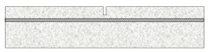
Figure 2. Reinforcing bars would make control joints in SOG largely ineffective.
Diaphragm Detailing
As mentioned in the introduction, and discussed in more detail below, SOG are often expected to act as braces or ties that resist horizontal reactions from building columns under wind and seismic loading. According to ACI 318-19 Section 18.13.3.2, if these columns form a part of the seismic-force-resisting system (SFRS) in buildings assigned to SDC C-F, the SOG must be designed and detailed as concrete diaphragms with a load path from the point of load to the resisting element. This means that the SOG must be reinforced for in-plane shear and flexure, and the engineer must consider the locations of joints without reinforcement. As in a typical concrete diaphragm, continuous reinforced chords might be required (Figure 3).
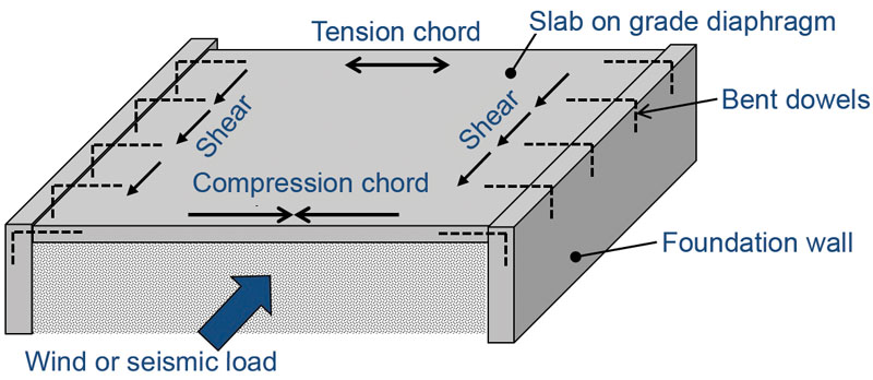
Figure 3. Slab on grade diaphragm.
Common Situations
Slabs with Hairpins
SOG are sometimes used for lateral support of columns in metal building systems (MBS), a.k.a. pre-engineered metal buildings. MBS typically include primary moment-resisting gable frames that carry secondary roof and wall members. One feature of these frames – and any “rigid” frames for that matter – is that their columns exert vertical and horizontal reactions on the foundations. MBS are often promoted based on their low cost, and the pressure is on to use inexpensive foundations for these buildings as well.
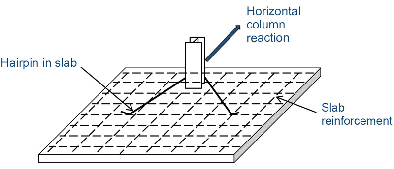
Figure 4. Hairpin in slab on grade.
The cheapest – and the most problematic – solution relies on hairpins, bent reinforcing bars hooked around the column anchor bolts and extending into the slab (Figure 4). The bars are assumed to carry the horizontal loading from the column into the SOG and then . . . where? A common assumption is that the SOG would somehow act as a tie that transfers the horizontal column reactions to the opposite side of the building or carry them to the soil by friction. The author has heard yet another idea: the slab carries the horizontal loading to the parallel exterior walls as a diaphragm. Some people do not even go that far. If the hairpins are tied to the slab, we are good, right?
Hairpins are cheap, and it takes little time to design them. But, as discussed above, using an SOG as a tie, brace, or diaphragm makes it into a structural slab constructed differently from a typical ground-floor slab. It is doubtful that those who hope to save money on MBS foundations expect an SOG with closely-spaced reinforcing bars, without any sawcut joints, and one that is positively connected to the perimeter foundation walls. However, that is the kind of SOG that would be necessary if hairpins were used.
There are multiple solutions for resisting horizontal column reactions that do not rely on any contribution of SOG. Among them are moment-resisting foundations and tie rods designed as grade beams. The author provides the design examples in Foundation and Anchor Design Guide for Metal Building Systems (McGraw-Hill, 2013). These foundations are reliable, but they might cost more than inferior alternatives such as hairpins.
Slabs Supporting Rack Structures and Mezzanines
Many warehouses and some industrial buildings contain multistory rack systems that support shelving – and even the roof structure. Rather than provide separate foundations at each rack post and isolate those from the floor slab, the typical solution is to support them on the SOG. Columns supporting mezzanines are also frequently placed directly on the slab. Several publications address the design of SOG subjected to concentrated loads, but they do not focus on the broader implications of using the slabs for structural purposes. Such SOG should be designed as structural slabs or as mats.
Soil-Retaining Walls Braced at the Top
These are often found in loading docks and similar structures where the surface behind the wall contains an SOG (Figure 5). The slabs bracing these walls serve structural purposes and should be designed as such.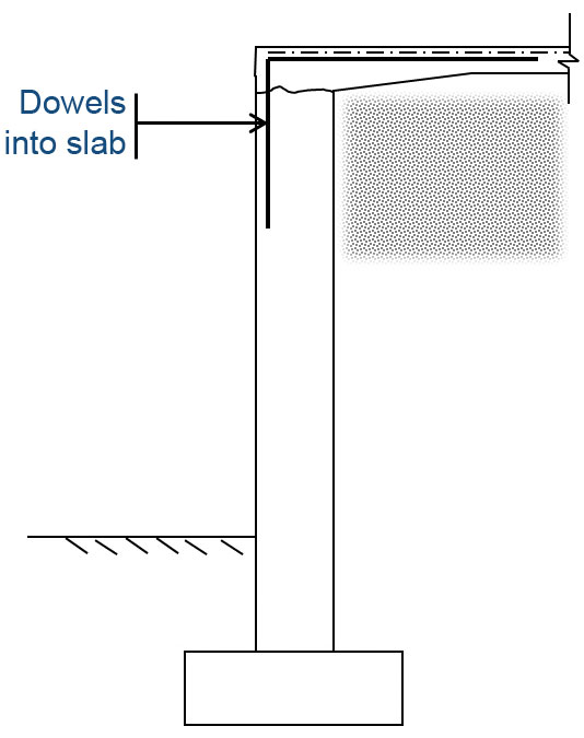
Some Unclear Situations
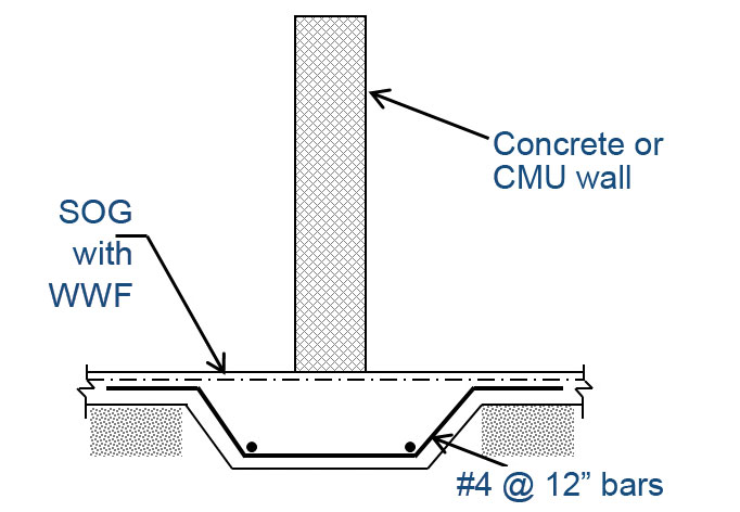
Figure 6. Thickened slab on grade supporting
lightly loaded concrete or CMU wall.
What about a concrete or masonry wall carrying relatively light loading and supported on a thickened SOG (Figure 6)? A column bearing on the spread footing integrally built with an SOG? An exterior loadbearing wall bearing on an integrally placed slab haunch (Figure 7)?
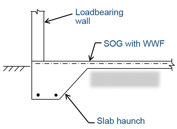
Figure 7. Slab on grade with integral haunch supporting loadbearing wall.
When an SOG of uniform thickness supports such walls or columns, the slab would clearly be considered structural. Must a thickened area be isolated from the rest of the SOG not to make the slab into a structural element? The codes are silent.■
Maximum Spacing of Primary Reinforcing Bars in Slabs on Ground
When slabs on ground (SOG) are considered structural slabs, ACI 318 provisions for maximum bar spacing apply. Typically, this spacing is taken as the lesser of three times the slab thickness or 18 inches. However, ACI 318-19 Section 24.3.2 further limits the maximum spacing of reinforcement to the amount indicated in Table 24.3.2. The maximum spacing is the lesser of:
Where cc is the concrete cover and fs is the stress in the reinforcement, which may be taken as 40,000 psi for rebars with fy = 60,000 psi.
According to ACI 318-19 Section 20.5.1.3.1, for concrete cast against ground cc = 3 inches, which is typical for the bottom bars in SOG. For the top bars, the cover may be taken as for concrete that is not exposed to weather or in contact with the ground, or ¾ inch for bars not more than No. 11. However, in SOG, the common practice is to place the top bars 1.5 to 2 inches below the surface of the slab “to minimize the bar shadowing and subsidence cracking” as ACI 360R-10 Chapter 8 points out.
Using these formulas, the maximum spacing for top bars, with cc = 1.5 inches is 11.25 inches; for the bottom bars with cc = 3 inches it is 7.5 inches. These values are quite low; the bars should be placed 1 inch below the top of the slab to keep the maximum spacing for the top bars to a more reasonable 12 inches.
The takeaway from this discussion is that the provisions of ACI 318-19 Section 20.5.1.3.1 are problematic for SOG. Following them leads designers to specify placing slab reinforcement only near the top – and with a smaller clear cover (1 inch) than referenced in ACI 360R (1.5 to 2 inches). Perhaps ACI should consider exempting reinforced SOG from the provisions of Chapter 20, but, as of now, these provisions apply to the slabs used for structural purposes.