
Analysis and Design
Renewable power generation nearly doubled in the past decade, growing from 382 million MegaWatt hours (MWh) in 2008 to 742 million MWh in 2018, contributing approximately 18% of total power generated in the United States in 2018. 13% (96 million MWh) of the total renewable power is solar from both small-scale and utility-scale installations. Small-scale installations typically include solar panels attached to buildings or other structures. Utility-scale installations are designed to supplement the power from the electricity grid; therefore, they consist of several rows of Photovoltaic (PV) modules. With a forecasted increase in the number of utility-scale installations and limited standardized design guidance for structural engineers to draw from, this article reviews the load criteria and the lessons learned from failures observed with such installations in the past decade.
The growth in demand for rooftop solar installations resulted in the development of the Structural Engineers Association of California’s (SEAOC) PV2-2012, Wind Design for Low-profile Solar Photovoltaic Arrays on Flat Roofs, followed by the inclusion of loading provisions in the American Society of Civil Engineers’ ASCE 7, Minimum Design Loads and Associated Criteria for Buildings and Other Structures, in 2016. SEAOC subsequently updated its report in 2017, referencing the provisions of the published ASCE 7-16 standard. These resources provide guidance on the loading and behavior of small-scale rooftop solar units; however, limited guidance is available for the design of utility-scale PV solar structures.
Utility-Scale PV Solar
Utility-scale PV solar installations consist of multiple rows, each housing several PV modules mounted on a structural supporting frame. Depending on the nature of this support system, these installations are classified as either Fixed-mount, Single-axis tracking (SAT), or Dual-axis tracking (DAT) systems. Fixed-mount systems consist of a supporting frame that is static and fixed, usually at an angle to the horizontal. In such systems, the angle of the solar panels relative to the ground stays constant in operation. In contrast, SATs and DATs enable the modules to “track” the sun during the day for enhanced efficiency. This improvement in efficiency is achieved by gradually adjusting the inclination and orientation of the modules during the day to achieve optimum sun exposure. SATs enable tracking in the East-West direction only, while DATs enable tracking in other directions.
Given the lack of guidance for the design of the tracker systems, design engineers noticed the similarities between these support structures and other structures covered in ASCE 7. Engineers applied the loading provisions of these other structures to the design of tracker systems, primarily for the wind load case. Most popular among these equivalent structures are monoslope free roofs. The panels on any of the tracker systems (fixed, SATs, or DATs) are, at any given point, at an angle to the ground and, therefore, subjected to forces from the oncoming wind. Hence, the similarities to these equivalent structures seemed reasonable on the surface. Unfortunately, this practice resulted in wind-induced failures of tracker systems exposed to winds that were substantially lower than ASCE 7-16 design wind speeds.
A better understanding of the assumptions used to develop the provisions associated with monoslope roofs is needed to explain why the behavior of SATs under wind loading is not the same as monoslope roofs. The various causes of wind-induced failures of solar trackers and the lessons learned from multiple investigations are discussed below.
SATs Failures and Lessons Learned
SATs consist of a tube section (called a torque tube), typically oriented with its longitudinal axis in the North-South direction (Figure 1). This torque tube supports regularly spaced lateral frames or purlins designed to accommodate the PV modules. During operation, the torque tube rotates about its longitudinal axis, positioning the PV modules to track the sun during the day. The rotation of the torque tube is either provided by a motor mounted on the tracker torque tube itself or through multiple rows connected to a lever arm. In both setups, the rotation of the trackers is controlled centrally (and associated with in-situ weather monitoring) to obtain uniform tracking of all rows within the PV field. Enabling rotation about the torque tube to track the sun unlocks the torsional degree of freedom not commonly considered. The interaction of this additional degree of freedom with the oncoming wind has led to unexpected failures.
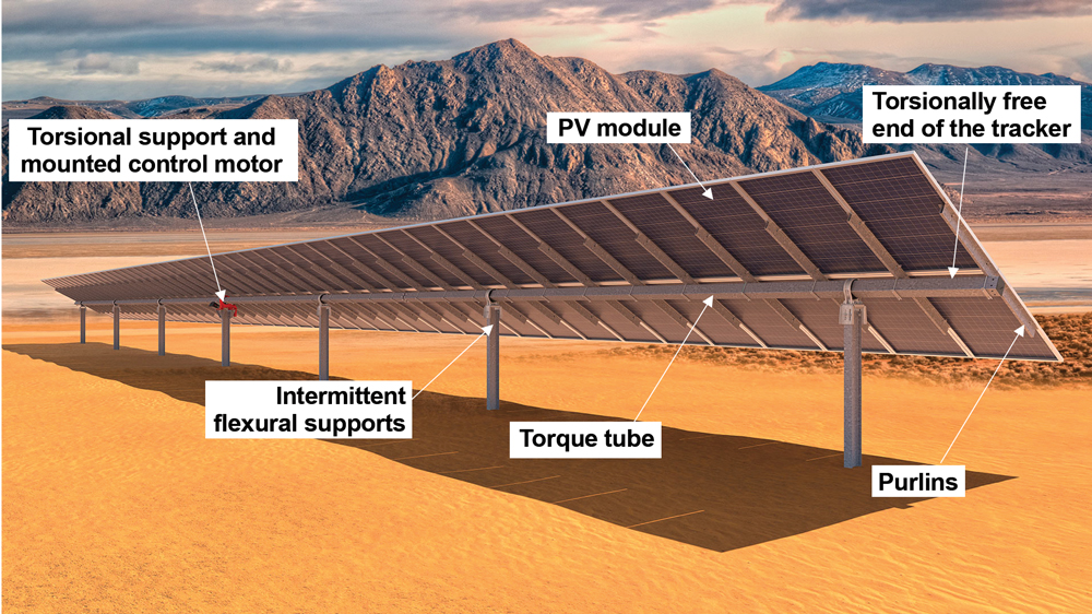
Figure 1. Illustration of a single-axis tracker system and its components.
Aeroelastic Instability
Aeroelasticity is the study of the interaction of aerodynamic, inertial, and elastic effects on a body or a system. Instability resulting from this interaction is typically characterized as an aeroelastic instability. The elastic effects (for the aeroelastic instability) originate from the torsional flexibility of the tracker systems. Increasing the stiffness to avoid instability inadvertently results in increased member sections that are not fully utilized in the strength limit state. The solution to this instability is an optimization problem, balancing the need for structural stiffness with underutilized strength. Aerodynamics increases the available solutions to this problem. To reduce the effective area subjected to wind, and corresponding wind loads, tracker systems are usually “stowed” flat (0-degrees or parallel to the ground) at higher wind speeds while not in operation. One of the aerodynamic solutions to the instability is to stow the PV modules at larger angles for higher wind speeds. Several tracker manufacturers consulted with wind engineers to devise optimal solutions that work best with their respective systems to resolve the instability.
Most of the commonly observed wind-induced failures of tracker systems exhibited evidence of an aeroelastic instability. Post-failure investigations typically show evidence of rows either completely displaced or a strong spatial concentration of displaced or damaged panels towards the rotationally free end of the torque tube. The aeroelastic phenomena observed with trackers ranged from the most common torsional galloping to a rarer torsional divergence. The mechanics of these phenomena are intricate and were partly introduced previously through the discussion of the failure of the Tacoma Narrows Bridge (Cheruka, 2018). Torsional modes of failure similar to the bridge, albeit lower mode numbers, are observed during field monitoring of SATs. These effects are beyond the scope of the ASCE 7 standard, and limited design guidance is available to resist them.
Load Magnitude
In addition to the aeroelastic instability effects, the magnitude of the applied wind loading is considerably influenced by the aeroelastic effects of the tracker systems. These effects are one of the primary reasons why applying loading provisions for equivalent structures from ASCE 7 to the design of SATs is not appropriate. The dynamics of monoslope free roofs and freestanding signs, considered when drafting the provisions in ASCE 7 standard, are not the same as the dynamics of SATs. The ASCE 7-16 monoslope free roof provisions assume that all edges of the monoslope roof are structurally supported. In contrast, PV module systems are supported by a central support that allows rotation about a central axis. This fundamental difference in support conditions and associated movement under wind loads leads to significant differences in the applied load magnitudes. Figure 2 compares the pressure coefficient, GCp, in ASCE 7-16 with some sample wind tunnel results. As evidenced, the present ASCE 7-16 provisions for monoslope free roofs do not adequately represent the observed loading on a tracker in a wind tunnel.
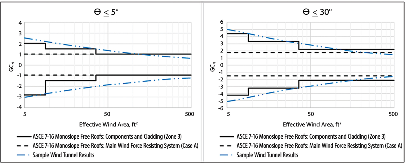
Figure 2. Comparison of sample wind tunnel results with ASCE 7-16 coefficients for angle with wind less than 5°.
Presently, there is a proposal under development, based on consensus wind tunnel coefficients from several laboratories, to incorporate wind load provisions for ground-mount solar assemblies into ASCE 7.
However, until standardized design guidance for the system being designed is available, structural engineers tasked with the design of tracker systems should consult a wind engineer for appropriate loading to minimize liability risk.
Connections and Bolts
A typical solar field incorporates thousands of tracker elements and associated framing, and ease of installation is an essential factor in the design of the modern tracker system. Hence, a typical tracker system includes pretensioned bolts that can be easily installed onsite. A common observation in several failed (and some operating) solar plants is a loss in pretension and loosening of bolts. Sometimes, poor installation during erection is the culprit for loose bolts. In-service vibrations due to wind response, albeit small, can also lead to a loss in pretension and bolt loosening. Loose bolts allow for unintended relative movements, which often compromise the stiffness of the tracker structural system and lead to undesirable aeroelastic effects. The designer can take some measures to better control the in-service vibrations and minimize the risk of bolt loosening. An understanding of the buffeting response (response to a sudden random impulse) of the trackers and the use of dampers successfully controlled these vibrations and limited bolt loosening in the field.
Another common observation with the pretensioned bolts on these trackers is bolt slip. The use of galvanized bolts for corrosion protection leads to an increased susceptibility for slippage of pretensioned bolts. Similar to loosening, bolt slip can lead to a host of issues ranging from relative movement at the splices to a deviation from the design angle of stow.
Load Application
Tracker systems are long and relatively flexible compared to commonly designed buildings, primarily in the torsional degree of freedom. This flexibility produces large rotations under load application, typically at the ends of the tracker torque tube. This rotation may occasionally be so large that the effective angle of attack (angle of the panels relative to the wind) may vary. For example, if the load application (load magnitude at 0 degrees) results in a 15-degree rotation at the end of the tracker, then the magnitude of load applied must be adjusted to accommodate the deviation from 0-degrees. In short, a nonlinear load application due to relative movement along the length of the tracker should be considered in the design. The extreme case of this is the static instability of torsional divergence, where the system never converges to a stable position. Even if stable, the applied loads may vary considerably and should be accounted for. When loads are procured from wind tunnel testing, the wind engineer must be consulted about this aspect of nonlinear load application to determine if this behavior is already accounted for in the provided loads.
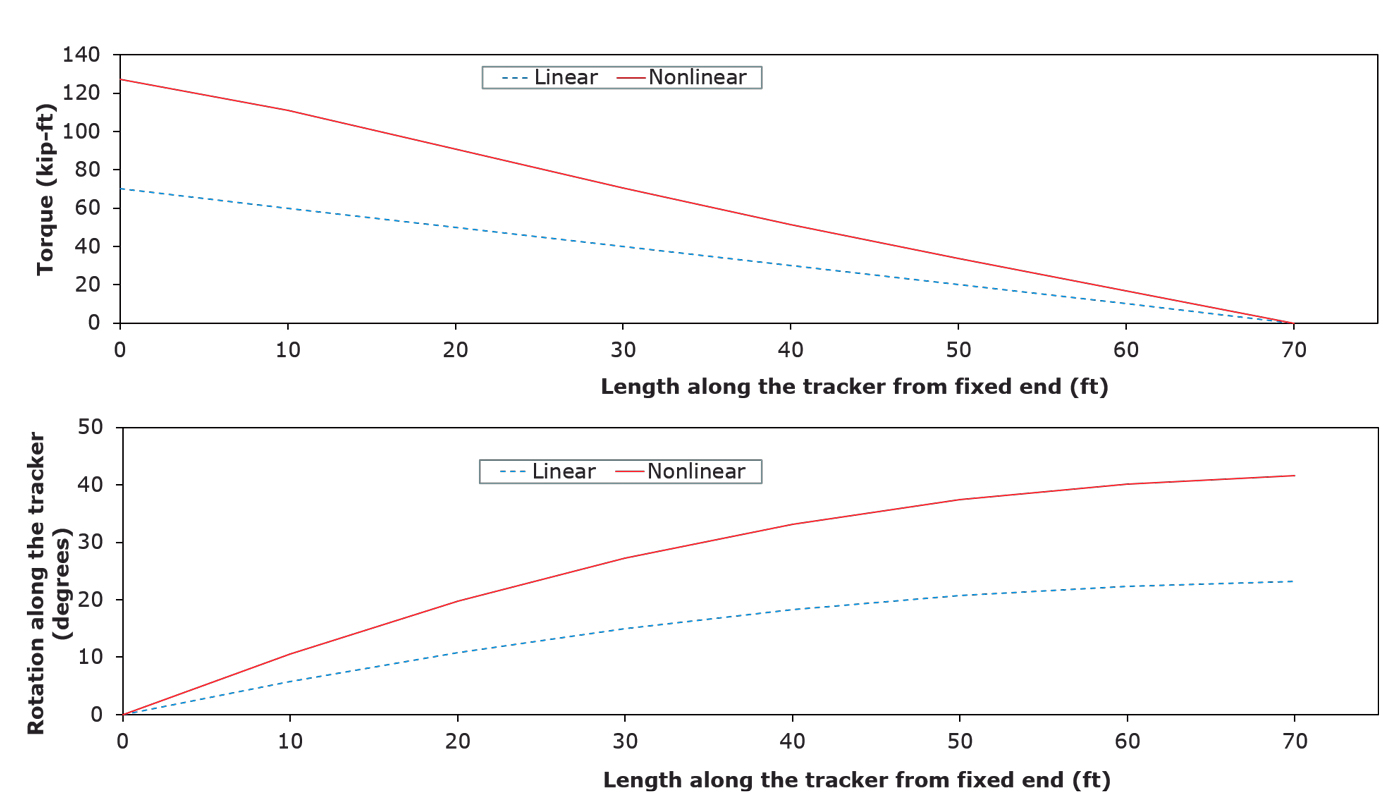
Figure 3. Results of non-linearity on tracker loading.
Figure 3 shows the increase in the applied load magnitude due to nonlinear effects. The figure is based on an HSS 4×4×1⁄8 torque tube under a uniform torsion of 1 kip-in/ft along the length of the torque tube. In this case, the cumulative nonlinear torque at the fixed end of the tube and the rotation at the free end of the torque tube is 1.8 times the values calculated using linear analysis.
Another factor often missed in load application is stow tolerance. The trackers are stowed while not in operation or under stow conditions (typically high wind speed events) to ensure safety. For example, a tracker stowed flat (or 0 degrees to the ground) at high wind speeds has a less effective area and thus observes lower wind loads. However, this stow position is not always exact, and some systems associate a tolerance as high as ±7.5 to 10 degrees. The structural engineer should verify the behavior (and safety) under stow conditions, including the stated tolerance.
Support Fixity
As discussed previously, SATs primarily act as cantilevers in the torsional degree of freedom. However, it should be noted that the “fixed” end of the cantilever is not always fixed. Often, they are connected to a motor or a lever arm that is used to control rotations during the day. The torsional restraint of these end connections is not sufficient to be deemed as a “fixed” support. The flexibility of the sole torsional support leads to challenges in the design. Deviation from fixity at the torsional support reduces the natural frequency of the system. Figure 4 shows the peak torque as a function of reduced frequency estimated using different methods. Reduced frequency is a non-dimensional number to combine the effects of the stiffness of the system (frequency, f), across wind dimension (L), and the wind speed (V). Since peak wind load magnitudes increase as natural frequency decreases, assuming fixity is not conservative.
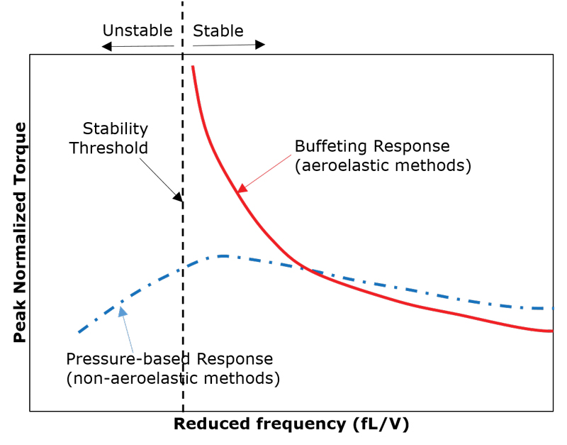
Figure 4. Schematic of aerodynamic loading as a function of reduced frequency.
Pressure-based methods use rigid models in the wind tunnel, and dynamic properties of the structure are mathematically modeled. As the frequency of the system is reduced (or the speed increased), the pressure-based methods tend to under-predict the peak torque indicating that stiffness is coupled with the observed loading. Hence, to accurately assess the wind load acting on the system, the buffeting response of the system must be evaluated using either numerical buffeting response analysis or aeroelastic model testing.
From a structural modeling standpoint, the conservative approach of modeling the support as a pin connection will not work because the system would be unstable (as the other end is torsionally free). In contrast, modeling the support as a fixed end may be unconservative and underestimates applied wind loads. It is thus advised to understand the motor system that is used to control the tracking. The connection between the motor and the torque tube should be studied to develop a reasonable estimate of the torsional stiffness at the support. It is also essential that the wind consultant is aware of the support stiffness conditions since there is a potential to affect the measured wind pressures. In-situ dynamic testing of mock-ups or test setups for natural frequencies have been performed by some system manufacturers to accomplish this.
Summary
The rapid growth in the demand for utility-scale solar power led to an increase in the construction of the trackers across the U.S. However, design standards have not kept up with this surge in demand, leading to multiple failures. From lessons learned through investigation of failures, the designer can mitigate the risk of failure by:
- Understanding the aerodynamics and/or consulting a wind engineer for potential instability, estimate of load magnitude, and load application procedure;
- Understanding the tracker system by learning the operational stow tolerance and support fixity;
- Considering in-service wind-induced vibration of the tracker and its influence on various components; and,
- Designing connections to ensure limited stiffness discontinuities by minimizing bolt slip or loosening.■
References
US Energy Information Administration (USEIA), US renewable electricity generation has doubled since 2008, www.eia.gov published March 19, 2019, accessed January 18, 2020.
SEAOC Solar Photovoltaic Systems Committee. (2012). SEAOC PV2-2012 Wind Design for Low-profile Solar Photovoltaic Arrays on Flat Roofs. Sacramento, California
ASCE/SEI 7 (2016), Minimum Design Loads and Associated Criteria for Buildings and Other Structures, American Society of Civil Engineers, Reston, VA
www.kiewit.com/plant-insider/current-issue/fixed-tilt-vs-axis-tracker-solar-panels accessed on January 18, 2020.
Cheruku, Sumanth (2018), Revisiting the Galloping Gertie, STRUCTURE magazine, July 2018, www.structuremag.org/?p=13425
Mahmoud, Hussam et al. (2016), ERDC/ITL TR-16-2, Causes of Pretension Loss in High-Strength Bolts, United States Army Corps of Engineers, Washington, DC
Donahue, Sean, Helwid, Todd, (2014), Slip Coefficients for Galvanized Structures, Draft report 4195, American Institute of Steel Construction, Chicago, IL. https://bit.ly/2AAsFI6
Denoon, Roy (2018), Wind Tunnel Testing for Tall Buildings, STRUCTURE magazine, June 2018, www.structuremag.org/?p=13256