
A Bluffer’s Guide
Wind tunnel testing is a ‘black box’ to many practicing structural engineers. This article strives to shine a small beacon inside the box and provide the reader with a foundation for asking sensible questions of wind tunnel laboratories. It is written from the author’s experience as a practicing wind engineer, an advocate for wind tunnel testing on major projects, and a client in receipt of wind tunnel test reports.
A common puzzle for design teams is knowing when a wind tunnel test will be of value. As a wind engineer, the obvious answer would be “always,” but the more honest response is “it depends.” The typical issues for which a wind tunnel test might be commissioned for a tall building (Figure 1) include life safety issues of accurate determination of local pressures and wind-induced structural loads and responses. Also, typical serviceability issues of pedestrian wind conditions and building exhaust dispersion that contribute to the public and occupant perception of the quality of the built environment are of concern.
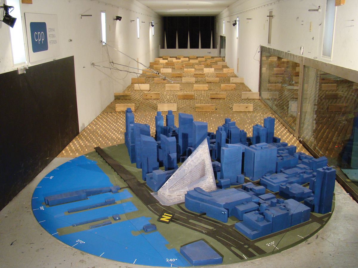
Figure 1. Wind tunnel pressure model.
Codes and Standards
Wind-induced structural loads and cladding pressures can normally be estimated by building codes or standards. One regularly asked question is, “Why would a wind tunnel test be more accurate than the code?” The simple answer is that all the values in the code were developed from wind tunnel tests and intended to envelop the majority of cases. However, almost all codes include numerous caveats to their applicability for unusual buildings or circumstances, where wind tunnel testing is mandated as an alternative route to compliance. As such, the codes should provide conservative values for the majority of ‘typical’ tall buildings in urban environments while a properly conducted wind tunnel test will give more accurate project-specific design values. These updated values will either result in lower-than-code values with consequent savings in construction cost, or capture unusual effects not covered by the code to ensure adequate design reliability.
In the design process, it is very often the structural engineer who takes responsibility for recommending whether wind tunnel testing is conducted. For many, this decision is predicated on the expectation of the significance of wind-induced strength-design lateral loads to the design, often based on how these might compare with the seismic lateral loads. This, however, does not take into account the savings that can be achieved in the façade design or ensuring that occupants will not be disturbed by overly frequent perceptible building motion.
With particularly slender buildings or those affected by local topography or excessive aerodynamic interference from neighboring buildings, the use of codes may not achieve adequate structural reliability. In these cases, the use of wind tunnel testing ensures that the desired levels of design reliability and robustness are met, consistent with the structural engineer’s professional responsibility. As performance-based design (PBD) gains more traction, wind tunnel testing will become an increasingly important part of achieving design objectives, something that is anticipated to be covered in an upcoming monograph from an ASCE Task Committee and an SEI Wind PBD Pre-Standard.
Test Types
There are three commonly used wind tunnel test types for the determination of wind-induced structural loads and responses for tall buildings. These are the high-frequency balance (HFB), high-frequency pressure integration (HFPI), and aeroelastic techniques.
The HFB and HFPI are the most common approaches and use rigid aerodynamic models. Both measure the wind forces exerted on the building model and, for high-rise buildings, the dynamic properties of the building are introduced mathematically into the analysis to determine the total response to the wind loading. The HFPI approach (Figure 2) is now applied to the majority of projects, as it uses the same model as the cladding pressure testing. Pressures measured simultaneously over the building surface are integrated to determine the overall wind loads applied to the building. However, for particularly architecturally complex buildings, it may not be possible to have a large enough number of pressure taps to map the pressure fields over the building with sufficient resolution. For very tall slender towers, the limited cross-section of the tower often provides a physical limitation to the number of pressure tubes that can be extracted from the model at once. In this case, HFB testing is the logical alternative.
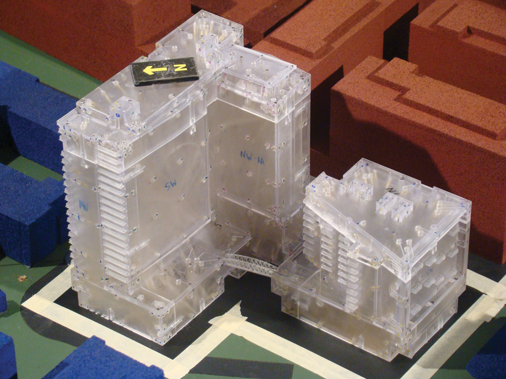
Figure 2. Close-up of a wind tunnel pressure model.
HFB testing (Figure 3) uses a lightweight model mounted on a very stiff balance to measure the applied forces at the base of the model. In this way, the HFB model is working as a mechanical integrator compared with the numerical integration of the HFPI approach. As the construction of an HFB model is less involved and more economical than a pressure model, this is also the technique that is used most commonly early in the design process where the final architecture may not yet be complete. This model is also easier to modify if a range of building shapes are being investigated. Shaping studies are sometimes used during concept design of particularly slender and wind sensitive towers to optimize building shape and minimize building responses. An appropriately designed HFB model can incorporate a number of adjustable features to investigate various architectural changes.
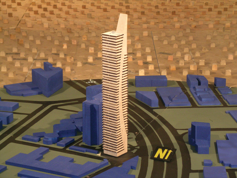
Figure 3. High-frequency balance model. Courtesy of b&w structural designs, llc.
The aeroelastic approach differs from the aerodynamic model approaches in that the model incorporates the appropriately scaled dynamic properties of the prototype structure: natural frequencies of vibration, mass characteristics, and damping ratios. The aeroelastic approach is generally more expensive than the aerodynamic techniques. The parameter which the aeroelastic modeling captures, which is not measured in either the HFB or HFPI approaches, is the aerodynamic damping. For most buildings, the aerodynamic damping is positive. This is beneficial in reducing the resonant dynamic response of the building. However, the degree of positive aerodynamic damping is invariably much smaller than the inherent structural damping and within the degree of uncertainty associated with the estimate of structural damping. The aeroelastic test is more important when initial aerodynamic test results show that there is the potential for strong cross-wind (or vortex shedding) response. As the wind speed approaches the peak for vortex-shedding, negative aerodynamic damping is generated, thus reducing the effective total damping of the building and increasing the building responses.
Wind Engineering Consultant
The first thing a trusted wind engineering consultant should be able to provide to designers is advice on what wind effects should be of interest to the design team. This includes advice about what testing and consultancy would be of value to a project, and identification of any design features that may be particularly wind sensitive or, conversely, beneficial in the performance of the development. Early consultation can help projects develop in a much smoother manner rather than waiting for unexpected results when the form and structure of a building are close to being fixed.
Once a wind engineering consultant is on board and a project has reached the stage of preparing for wind tunnel testing, then there should be regular interaction between the wind engineering, structural engineering, and architectural teams. The architectural team is responsible for the supply of the building geometry from which the wind tunnel test model(s) will be built. Generally, the wind engineering consultant will take responsibility for gathering information about the surroundings to build the proximity model. When the test models have been designed, drawings and/or 3D models should be provided to the design team for their checking and approval. This helps to ensure that the model reflects the current design and includes any critical changes that may have occurred since the original issue of architectural information. This will typically happen before the physical test model is constructed to allow for the incorporation of any modifications.
The wind engineering consultant should at all times be able to describe, and justify, the approach to testing being used. For the design team, key issues to check are that an adequate radius of surroundings buildings has been modeled. This is a balance of model-scale (for tall buildings this is typically between 1:200 and 1:500 depending on the building height) and the cross-section of the wind tunnel being used. For tall buildings, it would be normal to include a radius of at least 1200 feet around the building, although 1600 feet is more common, and any other significant buildings outside of this radius that would be expected to impact the flow onto the test building.
Reviewing Test Results
Most engineers do not have much exposure to wind tunnel testing and how to interpret and check results, but there are a few resources to aid in this. The first is to make sure that the testing has been conducted to a reasonable standard. This can be done with reference to a number of guides ranging from the descriptive ASCE Manual of Practice No. 67 on Wind Tunnel Studies of Buildings and Structures to the more prescriptive ASCE/SEI Standard 49-12, Wind Tunnel Testing for Buildings and Other Structures. A more concise document, created for design professionals working with tall buildings, is the Council on Tall Buildings and Urban Habitat (CTBUH) publication, Wind Tunnel Testing of High-Rise Buildings, which summarizes what should be expected from wind tunnel tests conducted for tall buildings.
The most obvious first check is to compare the loads and local pressures with code values. This is something that should also have been conducted by the wind tunnel laboratory and, if there are significant differences, this should have been highlighted and explained to the design team.
Local negative (or suction) pressures, so-called “hot spots,” that are larger than code values are not unusual in limited areas of the building. These are typically a result of very localized flow features, such as conical vortices that result most commonly from architectural discontinuities. However, peak positive pressures that are significantly larger than code values are a flag to raise questions, unless they can be shown to be a result of approach wind speed increases, as from channeling between upwind buildings.
The same type of channeling can lead to increased structural loads in the along-wind direction. However, the most common reason for high wind loads and responses of tall, slender buildings is cross-wind response, which will often govern for buildings with a height to width ratio of greater than 5 or 6. This is not something that is covered in U.S. loading codes, but simplified estimates can be obtained from online estimators and overseas design standards. An example of base moment response dominated by cross-wind response is shown in Figure 4, identified by a rapid increase in the dynamic response at a wind direction orthogonal to the load while the mean load is close to zero.

Figure 4. Graph showing strong cross-wind response.
A more common query is when loads are significantly lower than code values. This can occur when the building is very sheltered by its neighbors. ASCE-7 has a lower limit on loads from wind tunnel tests to account for the removal of such adjacent buildings unless it can be shown that removing such significant sheltering buildings still results in low loads, in which case lower limits can be applied. If, however, a wind tunnel reports loads significantly lower than the 80% cut-off used by ASCE-7, this is a good cue for the design team to start asking questions.
Occasionally, a structural engineer will get the opportunity to compare wind tunnel results from two different laboratories for the same building. These almost never agree exactly but should be within 10 to 15% of each other. Where differences are larger, the discrepancies are predominantly due to the interpretation of the site wind climate. While pressures vary with the wind speed squared, dynamic responses can vary with the wind speed cubed or greater. If there is one thing for a structural engineer to check and understand, it is the wind engineering consultant’s interpretation of design wind speeds to ensure that they are both scaled appropriately to any local statutory requirements and that directionality can be rationally explained with respect to the wind climate and surrounding terrain.
Conclusion
Wind engineering is a combination of art and science, and it is important for structural engineers to understand just enough to check that the right studies are being conducted and, if not the reasons for unusual results, the appropriate questions to ask to elicit explanations.▪