
Part 1: Investigation, Repair, and Rehabilitation
Part 1 of this 2-part article addresses structural behavior and assessment methods. Part 2 will focus on analysis and repair options.
Due to increasing costs and restrictions associated with redevelopment (replacement) of existing buildings, as well as municipal initiatives geared to promote the preservation of the existing building stock, repair and rehabilitation of existing buildings have become economically and politically attractive options for property owners. Adaptive and direct reuse of old, historical, and sometimes archaic structures requires careful engineering assessment of their ability to continue to safely perform under current building code requirements. This is no easy endeavor and requires a thorough investigation of existing conditions, analysis to determine in place structural capacity, and creativity to conceive effective, yet practical and economically feasible solutions.
Buildings featuring timber bowstring trusses are no exception. Bowstring trusses were a popular solution for structurally supporting roofs from the 1900s through the 1950s, especially in buildings where large, open spans were desired (manufacturing facilities, garages, warehouses, among others). Many buildings with this type of roof support are still in service today; given their age and inherent vulnerability (e.g., to environmental, load, and other factors), their adequacy and reliability have become a common reason for concern.
Behavior and Original Designs
Bowstring trusses typically feature a parabolically shaped top chord constructed of several wood elements (laminations) mechanically connected through the depth of the member. The bottom chord is often constructed of straight timber members with bolted splices. Both the top and bottom chords consist of two parallel members separated by a gap. The gap accommodates connections to vertical and diagonal web members which frame in between the chord members. The web elements are either discrete members or are a lattice system (continuous arrangement of web members) (Figure 1). The top and bottom chords are typically connected by a U-shaped steel strap that wraps around the end of the truss and is bolted to the chord members. The ends of the truss bear on columns or are situated inside pockets within masonry walls. The typical span for these trusses is between 50 to 100 feet and the typical height is between 10 to12 feet.
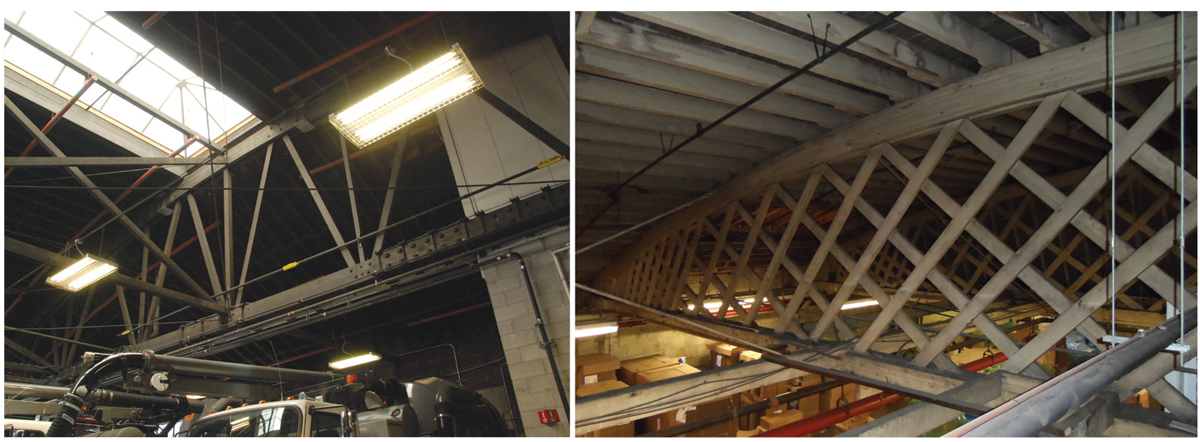
Figure 1. Bowstring trusses in which web elements are discrete (left) and are a lattice system (right).
Bowstring trusses structurally behave as a tied arch. The shape of the top chord (parabolic) results in generally uniform compressive stresses in top chord elements under uniform loads. The thrust forces at the ends of the top chord are resisted by the bottom chord, which acts as a tie; these forces are transferred to the bottom chord through the U shaped steel straps at the ends of the truss. Due to this arch like behavior, stresses in web members are relatively small under uniform load. These structures were developed (and designed) to withstand dead, live, snow, and wind loads, which general practice and most building codes in effect at the time of construction considered as uniformly distributed loads. Generally, snow drift loads, non-uniform wind loads, point loads (e.g., due to mechanical units on the roof), and seismic loads were not considered at the time of original construction.
Field Investigation
Two of the most significant challenges when investigating bowstring trusses are lack of documentation and restricted access. Drawings of existing bowstring trusses are rarely available. When this is the case, evaluation of the truss structural capacity must rely solely on field documented information; therefore, performing a thorough visual inspection is paramount. However, up close access to all truss members and their connections, while necessary, is often very challenging due to existing obstructions and concealed conditions. A combination of small aerial lifts and ladders usually allow navigation through existing equipment and hung features to achieve sufficient access.
Even though each structure presents unique features, once access is achieved, most field investigations follow the same methods. A discussion on conventional investigation methods, along with typical and recurring distress/deterioration mechanisms found by the authors in recent investigations, is presented below.
Typical Investigative Methods
General Visual Inspection
This includes careful documentation of the general truss configuration, member sizes, top and bottom chords construction, connection details, and boundary and support conditions. General roof characteristics (e.g., location and height of parapets, truss spacing, roofing construction) should also be documented during this phase. Finally, observation of readily visible distress (e.g., full member splits, shakes, rot, etc.) is critical. General observations of the overall condition of the structure should be accompanied by more specific observations in focus areas.
Non-Destructive Testing
Often, decay in wood elements is hidden (material properties can be significantly affected without a change in appearance). Therefore, non-destructive techniques can and should be employed to supplement and confirm visual observations. Hammer sounding, surface pick tests, moisture-meter readings, and resistance to drilling with a resistograph are all methods both effective and relatively simple to implement. Resistograph tests are especially useful to determine the extent of deterioration (in many cases concealed) through the width and depth of large-sized members (Figure 2). These tests add time to the investigation; as such, their frequency (i.e., the number of tests) and location should be carefully considered to allow for a sufficiently representative sample.
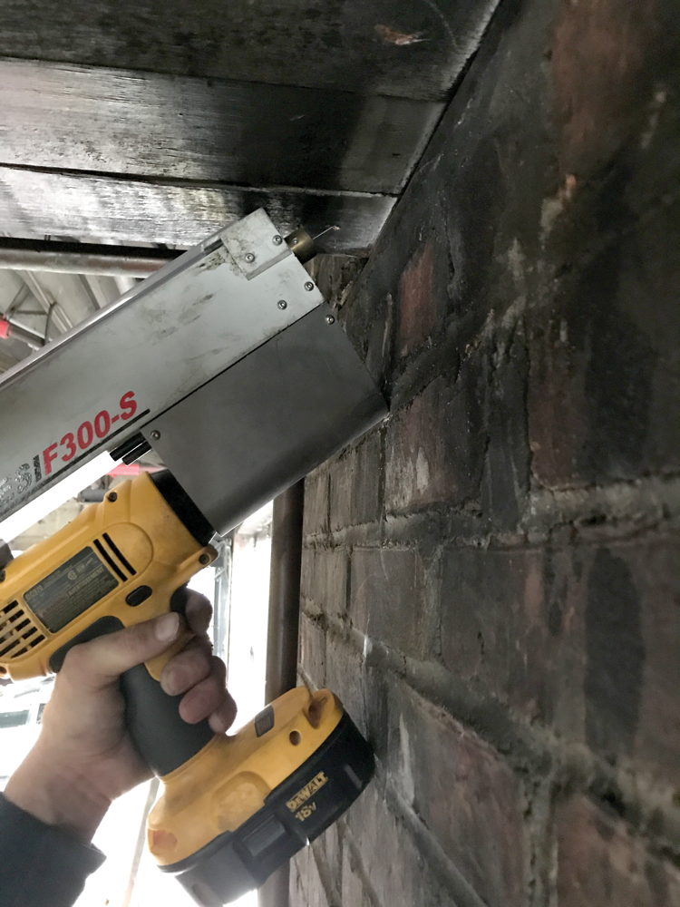
Figure 2. Resistograph test to determine the extent of deterioration at the bearing end of a bowstring truss embedded in masonry.
Core Sampling
Core samples are typically extracted for microscopic examination and species identification. Wood species, member composition (e.g., the presence of laminations), and damage at a cellular level can be assessed by a qualified professional based on the microscopic evaluation of core samples. Because there might be more than one species of wood in a single truss, extracting at least one core sample from each type of member (i.e., top chord, bottom chord, and web members) is a good practice to follow.
Visual Stress Grading
This technique includes close-up inspection of wood members to identify and locate grade-affecting natural characteristics (defects) in wood, such as knots, the slope of grain, checks, and splits. Size, type, and location of knots, as well as the slope of grain, are typically the two characteristics that have the most significant effect on the strength of a wood member. Presence and distribution of natural defects, wood species, and moisture content can be used to calculate allowable design values for each visually graded member. This is done in accordance with methodology outlined in ASTM D245, Standard Practice for Establishing Structural Grades and Related Allowable Properties for Visually Graded Lumber. Applying this method in the field is time-consuming; therefore, it is typically performed on a limited, appropriately-sized, and representative sample of truss members. The sample should include several members of each type and size throughout multiple trusses.
Probing
Some truss features may be concealed at the time of the investigation. For example, the bearing ends may be embedded in masonry, connection details may be concealed by hung components, and existing paint (or other finishes) may impede identification of characteristics that affect stress grading (such as knots). Exposing these conditions may require making exploratory probes (Figure 3) and removing paint or finishes. The probing campaign should be carefully planned to minimize disruption to the existing operations.
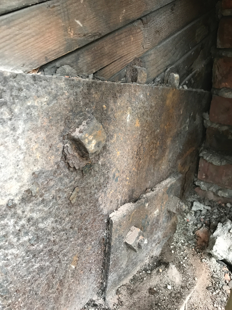
Figure 3. Exploratory probe opening at the bearing end of a bowstring truss embedded in masonry.
Deterioration Mechanisms
Drying Shrinkage
Timber members are typically green at the time of installation (moisture content greater than 19%). As the members dry in service, they shrink. Restrained shrinkage may result in checks and splits or other compatibility-driven distress. For example, shrinkage related issues can significantly compromise the dowel bearing strength of bolts, possibly leading to connection failure. Engineers performing the field inspection should pay close attention to connections that include multiple rows of bolts (especially if they include steel plates that can constrain and distress wood members), splices, and connections in tension-loaded members.
Exposure to Moisture
Wood is susceptible to fungal deterioration (decay or rot) when consistently or repeatedly exposed to moisture; decay will likely occur when the wood reaches a moisture content of 20% or higher. This moisture content can be easily achieved near roof leaks (near gutters or around the perimeter of skylights), or at the ends of trusses embedded in pockets within masonry walls. Ends of trusses embedded in masonry are especially susceptible to this type of deterioration, given their inability to dry once they have been exposed to moisture. Additionally, the presence of water at truss ends can also lead to corrosion of the U shaped steel straps. Embedded bearing ends should be investigated through a combination of probing, visual observations, surface pick tests, and resistograph tests.
Conclusions
The assessment of bowstring trusses should identify all features that would affect the ability of the structure to function as intended and designed. These include loads that differ from the original design loads (due to change in use, added mechanical equipment, the evolution of building codes, etc.) and deterioration of specific members of the truss. An experienced investigator should select the appropriate investigation techniques to identify the deterioration mechanisms affecting the structure. Then, rather than just addressing the symptoms (e.g., rot, fracture, etc.), the repair strategy for bowstring trusses, just like for any other structure, must focus on, consider, and eliminate the underlying sources of identified issues or problems.▪