
A Trial and Error Process
Concrete tilt-up buildings are a common subset of a class of building referred to as rigid-wall-flexible-diaphragm (RWFD) structures. Common diaphragm types are plywood, oriented strand board, or metal deck. Masonry wall buildings with flexible diaphragms are also examples of RWFD buildings. Tilt-ups have performed poorly in past earthquakes, with the primary weakness being the anchorage between walls and roof.
In the seismically active western United States, design was governed primarily by the Uniform Building Code (UBC) until the advent of the International Building Code (IBC). Before the 1973 UBC, it was common practice by design engineers to use the nailing of the plywood roof diaphragm to the wood ledgers (which are bolted on the inside face of the walls) as the de facto anchorage for out-of-plane wall forces (Figure 1). This indirect tie arrangement relied on the wood ledger in cross-grain bending and the plywood panel in tension near its edge. Cross-grain bending and tension are both very weak material properties of wood. Wall anchorage design forces before the 1973 UBC were specified as 0.2Wp under allowable stress design (ASD), where Wp is the tributary wall weight being anchored. In the 1971 San Fernando earthquake, the wall anchorage in many tilt-up buildings performed poorly. The use of this indirect wall tie led to wood ledgers failing in cross-grain bending and to plywood edge nailing tearing through panel edges from the wall anchorage tension loads. Partial roof collapses and wall collapses were common in the areas of strong ground motion.
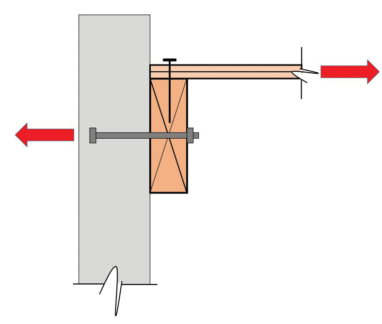
Figure 1. Typical Pre-1973 UBC wall-to-roof anchorage detail (West Coast U.S.).
Subsequently, the 1973 UBC and 1976 UBC adopted detailing provisions intended to prevent such failures. Beginning with the 1973 UBC, the requirement for a positive and direct wall anchorage was introduced, and reliance on cross-grain bending in wood was expressly prohibited in the wall anchorage system. Furthermore, to transfer the heavy perimeter walls’ seismic anchorage forces effectively into the main roof diaphragm, the concept of continuous ties or crossties was explicitly required to collect and distribute the anchorage forces uniformly across the diaphragm depth for further distribution to shear walls (Figure 2). Because of the complexity and cost of providing the necessary repetitive crosstie connections across the roof structure, the concept of the sub-diaphragm was introduced in the 1976 UBC as a design approach for transferring forces from the individual wall ties to the continuous crossties. Sub-diaphragms are smaller portions of the main diaphragm, located adjacent to walls, and span between the continuous crossties. The 1976 UBC also increased the wall anchorage design force in areas of high seismicity from 0.2Wp to 0.3Wp through the inclusion of a 1.5 default site factor under ASD procedures.
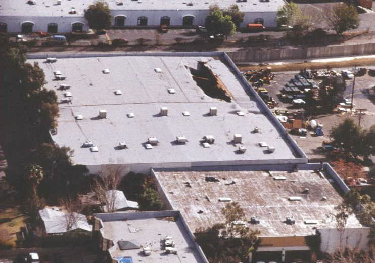
Figure 2. Diaphragm failure due to inadequate continuous cross-ties for wall anchorage. Courtesy of Doc Nghiem.
Fewer, but similar, wall-to-roof anchorage failures were observed in the 1984 Morgan Hill and 1989 Loma Prieta earthquakes. More significant was the strong motion data recorded in several undamaged instrumented tilt-up concrete buildings with flexible wood roof diaphragms. Research determined that the roof diaphragm accelerations were amplified three to four times that measured at the ground level, suggesting that wall anchorage forces were likely underestimated by the existing UBC provisions for a design level earthquake. This created the basis for an update in the 1991 UBC, increasing wall tie forces in the center half of the diaphragm span by 50% from 0.3Wp to 0.45Wp for seismic Zone 4 under ASD procedures.
The 1994 Northridge earthquake was the first test of modern, post-1976 UBC provisions for wall anchorage to flexible wood roof diaphragms under very strong shaking. Hundreds of buildings were severely damaged due to inadequate wall anchorage, often resulting in partial roof collapses as seen in Figure 3. The poor performance of the pre-1973 UBC tilt-up and masonry industrial buildings was not a surprise. However, the amount of damage in buildings designed to more modern codes was unexpected. Most notably, steel anchorage straps fractured through the net section in tension causing a sudden loss of anchorage strength, damage concentrated at the tops of pilasters due to inadequate reinforcing, and subpurlins with eccentric anchors failed.
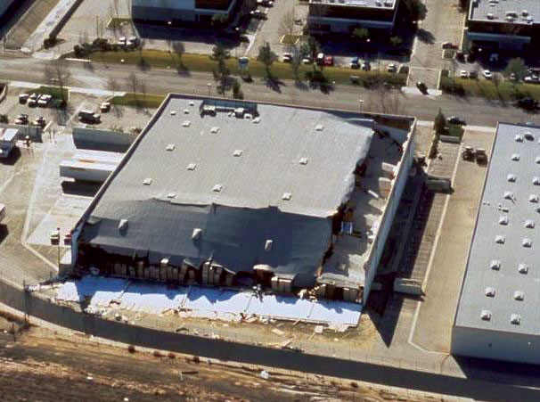
Figure 3. Damage to tilt-up concrete building due to loss of wall anchorage during the 1994 Northridge earthquake. Courtesy of EERI.
At the time of the earthquake, the City of Los Angeles was developing Division 91 for the voluntary retrofit of pre-1976 tilt-ups. After the earthquake, this document was updated and made mandatory for the repair and retrofit of these older tilt-ups. A second voluntary document (Division 96) was developed for post-1976 tilt-ups. Division 91 served as the basis for Appendix Chapter 5 of the 1997 Guidelines for Seismic Retrofit of Existing Buildings (GSREB); GSREB Appendix Chapter 5 eventually became Appendix Chapter 2 of the International Existing Building Code (IEBC). The appendix chapter has served as the basis of many voluntary upgrades as well as ordinances adopted by various jurisdictions. All these documents recognized that overstress of the diaphragm in shear is not a likely source of the collapse of these buildings. The idea of prioritizing the wall anchor system components and de-emphasizing the wall panels and other components when retrofitting is discussed in detail in the Structural Engineers Association of Northern California (SEAONC) document, Guidelines for Seismic Evaluation and Rehabilitation of Tilt-up Buildings and Other Rigid Wall/Flexible Diaphragm Structures. ASCE 41 can be used for retrofits that are more comprehensive when it is expected that wall panel deficiencies may exist (e.g., large openings).
There were substantial changes in the design requirements for new tilt-ups after the Northridge earthquake. The first group of changes was made in the 1996 UBC accumulative supplement, and further changes were made in 1997 UBC.
Wall anchorage damage to post-1976 UBC buildings in the Northridge earthquake was attributed to several causes. A significant factor was the lack of steel strap connection ductility and overstrength to accommodate the very large roof accelerations that occurred. With prior research indicating that rooftop accelerations may be three to four times the ground acceleration, code writers of the 1997 UBC decided that, instead of relying upon connection ductility, it was more appropriate to elevate the wall anchorage design forces up to expected levels. As a result, wall anchorage forces at the roof were increased to 0.80Wp using strength-level design provisions (Figure 4).
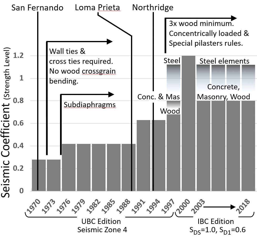
Figure 4. Evolution of UBC/IBC provisions for wall anchorage to flexible diaphragms
(Lawson et. al 2018).
Also, connection material-specific load factors (1.4 for steel, 0.85 for wood, 1.0 concrete/masonry) were specified to obtain more uniform demand-to-capacity ratios within the anchorage connection considering expected material over-strengths.
Poor quality control was also judged as a major contributor to the observed damaged. Observed deficiencies included:
- Missing ties at tops of pilasters
- Missing bolts at the connection of girders to pilasters
- Slack in installed anchorages including straps and rods
- Gross eccentricity due to misalignment of anchors
- Shimming that allowed bending of bolts
- Oversized bolt holes resulting from drilling without a jig to keep the drill bit perpendicular to the member
Such deficiencies demonstrated the need for diligent inspection and more involvement of the engineer via structural observation.
Detailing and design requirement improvements made because of post-Northridge observations included:
- Recognition of two-way action of wall panels due to the stiffening effect created by pilasters causing increased wall anchorage load reactions at the pilaster top.
- Prohibition of the use of one-sided eccentric wall anchors unless demonstrated adequate by calculation.
The increased wall anchorage forces, as well as the improved detailing and design requirements, were introduced into the 1997 UBC and have changed little under the IBC since then (Figure 4). More importantly, these provisions have yet to be tested in the field by a strong earthquake. Recent numerical modeling studies using non-linear time history analyses indicate that the wall anchorage force levels are likely appropriate under a design level earthquake (Lawson et al., 2018). However, it is possible that, if the wall anchorage weaknesses are now resolved, unacceptable inelastic behavior may appear in a new part of the structure previously not considered problematic. Currently, one such location under closer scrutiny is the flexible diaphragm.
This research into the expected building performance of RWFD structures under design and maximum considered earthquakes was conducted using numerical modeling. Several building archetypes were subject to a series of incremental dynamic, non-linear time history analyses to evaluate the estimated margin from collapse using FEMA P695, Quantification of Building Seismic Performance Factors. Findings indicate that a different approach to the design methodology can improve the margin against collapse to acceptable levels, and an alternate design procedure for RWFD buildings utilizing wood structural panel diaphragms is proposed in FEMA P-1026, Seismic Design of Rigid Wall–Flexible Diaphragm Buildings: An Alternate Procedure. This alternative approach utilizes independent response modification coefficients R, over-strength factors Ωo, and deflection amplification factors Cd for the diaphragm, in conjunction with a two-stage analysis procedure similar to that used for podium buildings. Currently, this alternative design methodology is being evaluated for possible inclusion in the next NEHRP Recommended Seismic Provision for New Buildings and Other Structures, and additional research work is on-going to evaluate similar recommendations with steel deck diaphragms.
With all that has been done in response to the 1994 Northridge earthquake and the recent P-1026 alternate procedure, the hope is that there will be few surprises with the performance of the newer building stock. However, such claims have been made in the past after a series of code changes have been made or lessons learned have been forgotten. It is possible that a new weak link will appear the next time the ground shakes hard in an area with a large stock of RWFD buildings. And, of course, the older buildings (un-retrofitted or retrofitted to earlier code provisions) remain a concern until they are appropriately updated.■
References
Lawson, J., Koliou, M., Filiatrault, A., and Kelly, D., “The Evaluation of Current Wall-to-Roof Anchorage Force Provisions for Single-Story Concrete and Masonry Buildings with Lightweight Flexible Diaphragms;” SEAOC 2018 Convention Proceedings, Structural Engineers Association of California, Palm Desert, California, 2018.