
Grade 60 reinforcing steel, with a yield strength of 60,000 psi, is the most commonly used grade in North America. Recent advances have enabled reinforcing steels of higher strengths to be commercially produced.
High-strength reinforcing bars (HSRB) are typically considered to be any reinforcing bar with a yield strength greater than 60,000 psi. This article presents pertinent information on material properties, the American Concrete Institute’s ACI 318, Building Code Requirements for Structural Concrete and Commentary, requirements and limitations, and some of the main benefits of using HSRB in reinforced concrete building structures.
The following is a brief history of the appearance and adoption of the various grades of reinforcing bars in ASTM specifications and ACI 318:
- Grades 33, 40, and 50 were in common use from the early 1900s through the early 1960s.
- Grades 60 and 75 reinforcing bars appeared in 1959 with the publication of ASTM A432 and ASTM A431, respectively.
- The 1963 edition of ACI 318 allowed the use of reinforcing bars with a yield strength of 60,000 psi.
- In 1968, ASTM A615 first appeared, which included Grades 40, 60, and 75 deformed reinforcing bars.
- Grade 75 bars appeared in the 2001 edition of ASTM 955, and Grade 100 bars appeared in the inaugural 2004 edition of ASTM 1035. The 2007 editions of these specifications first appeared in ACI 318-08, with ASTM 1035 containing requirements for both Grade 100 and Grade 120 bars.
- A yield strength of 100,000 psi was permitted for confinement reinforcement in the 2005 edition of ACI 318 for use in non-seismic applications and then in the 2008 edition of ACI 318 for use in seismic applications.
- The 2009 editions of ASTM A615 and ASTM A706 were the first to include requirements for Grade 80 reinforcing bars, which were adopted into the 2011 edition of ACI 318.
Material Properties
The design of any reinforced concrete member must satisfy the fundamental requirements for strength and serviceability as prescribed in ACI 318. With respect to reinforcing bars, the basic mechanical properties that are important in achieving safe and serviceable designs are:
- Yield strength, fy
- Tensile-to-yield strength ratio, fu/fy
- Strain (elongation) at tensile strength
- Length of yield plateau
Depicted in Figure 1 are typical tensile stress-strain curves for ASTM A615 reinforcing bars of Grades 60 and 100. The initial elastic segments of the stress-strain curves are essentially the same for both grades. Also, unlike Grade 60 reinforcing bars, a well-defined yield plateau for the Grade 100 reinforcing bars is not evident.
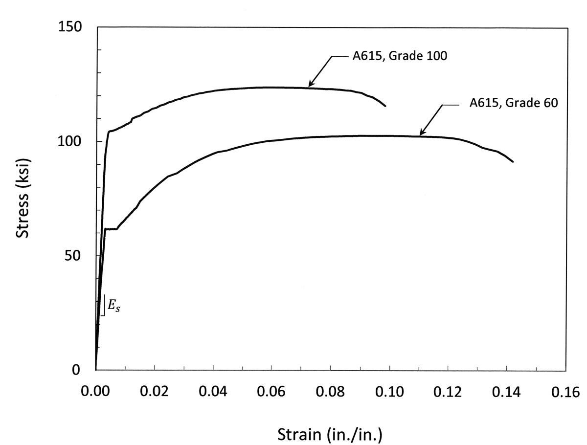
Figure 1. Stress-strain curves for A615 reinforcing bars of Grades 60 and 100.
The stress-strain curves for some types of Grade 100 reinforcing bars can be more rounded than the one shown in Figure 1; these are commonly referred to as round house or continuously yielding curves (Figure 2). After an initial linear-elastic segment, a gradual reduction in stiffness occurs; behavior becomes nonlinear before reaching a yield strength, fy, that is defined by the 0.2% offset method. This is followed by gradual softening until the tensile strength, fu, is reached.
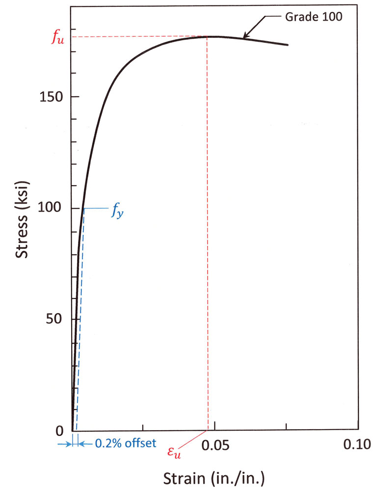
Figure 2. Rounded stress-strain curve for Grade 100 reinforcing bars.
In general, the tensile-to-yield strength ratio, the elongation at tensile strength, and the length of the yield plateau all decrease (or, in the case of the yield plateau, can become nonexistent) as the yield strength increases.
Limitations and Requirements
Tables 20.2.2.4a and 20.2.2.4b of ACI 318-14 contain the latest requirements and limitations for non-prestressed deformed reinforcement and non-prestressed plain spiral reinforcement, respectively. Limits for non-prestressed deformed reinforcement are given in the Table.
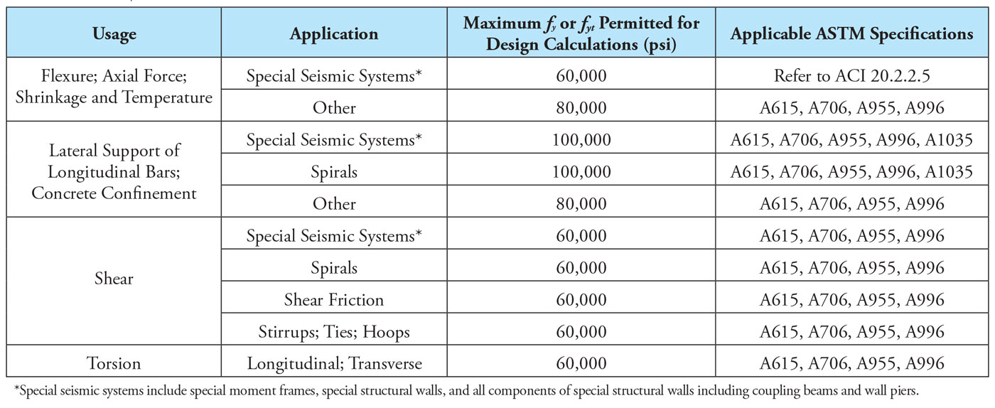
Table of limits for non-prestressed deformed reinforcement.
The yield strength of compression reinforcement is limited to 80,000 psi for use in applications other than special seismic systems. This limit is imposed because bars with yield strengths greater than approximately 80,000 psi will not contribute to increased compression capacity; at a strain of 0.003 at the extreme concrete compression fiber of a reinforced concrete section (the strain assumed at crushing of the concrete), the maximum usable stress in the reinforcing steel would be 87,000 psi based on linear-elastic behavior (ACI 22.2.2.1). Note that Grade 100 longitudinal reinforcement may be used in columns, provided the aforementioned limit of 80,000 psi is used in the calculations in accordance with ACI 318.
The limit of 60,000 psi for shear and torsion reinforcement is intended to control the width of inclined cracks that tend to form in reinforced concrete members subjected to these types of forces. References to research that supports the use of 100,000 psi reinforcing bars for lateral support of longitudinal bars and concrete confinement, including special seismic systems, can be found in ACI R20.2.2.4.
Only deformed longitudinal bars conforming to (a) and (b) below are permitted by ACI 318-14 in special seismic systems (special moment frames, special structural walls, and all components of special structural walls including coupling beams and wall piers) to resist the effects caused by flexure, axial force, shrinkage, and temperature. Higher grades of reinforcement were not included because, at that time, there was insufficient data to confirm the applicability of existing ACI 318 provisions for members with higher grades of reinforcement. These special systems are required in structures assigned to Seismic Design Category (SDC) D and higher.
Deformed longitudinal reinforcing bars used in structures assigned to SDC D or higher must conform to the following provisions (ACI 20.2.2.5):
(a) ASTM A706, Grade 60
(b) ASTM A615, Grade 40 provided the requirements in (i) and (ii) are satisfied; and ASTM A615, Grade 60 provided the requirements in (i) through (iii) are satisfied.
(i) Actual yield strength based on mill tests does not exceed fy by more than 18,000 psi.
(ii) The ratio of the actual tensile strength to the actual yield strength is at least 1.25.
(iii) Minimum elongation in an 8-inch gauge length must be at least 14% for bar sizes #3 through #6, at least 12% for bar sizes #7 through #11, and at least 10% for bar sizes #14 and #18.
In (i), the upper limit is placed on the actual yield strength of the longitudinal reinforcement in special seismic systems because brittle failures in shear or bond could occur if the strength of the reinforcement is substantially higher than that assumed in the design (higher strength reinforcement leads to higher shear and bond stresses).
In (ii), the requirement that the tensile strength of the reinforcement is at least 1.25 times the yield strength assumes that the capability of a structural member to develop inelastic rotation capacity is a function of the length of the yield region along the axis of the member. It has been shown that the length of the yield region is related to the relative magnitudes of nominal and yield moments; the greater the ratio of nominal to yield moment, the longer the yield region. Inelastic rotation can be developed in reinforced concrete members that do not satisfy this condition, but they behave in a manner significantly different than members that conform to this provision.
In (iii), the required minimum elongations for ASTM A615, Grade 60 reinforcement were added in ACI 318-14 and are the same as those required for ASTM A706, Grade 60 reinforcement.
Benefits and Limitations
Utilizing HSRB in concrete members may result in smaller bar sizes and/or a fewer number of bars compared to members reinforced with Grade 60 or lower bars. It may also permit smaller member sizes. By specifying HSRB, the following may be attained:
- Lower placement costs
- Less congestion, especially at joints
- Improved concrete placement and consolidation
- Smaller member sizes
- More useable space
Consider the reinforced concrete column illustrated in Figure 3a. For architectural reasons, the cross-sectional dimensions are limited to 18 inches. Assuming that the column is non-slender and that it is subjected to a concentric factored axial force Pu = 1,700 kips, the required longitudinal reinforcement using Grade 60 reinforcement is 12- #9 bars (ρg = 3.7%) with f’c =10,000 psi. This is a relatively large reinforcement ratio and at locations of lap splices, ρg = 7.4%, which is slightly less than the code-prescribed maximum value of 8%. Additionally, the clear spacing between the longitudinal bars is about 3 inches. The combination of large reinforcement ratio and relatively small clear spacing could cause considerable congestion issues at the joints.
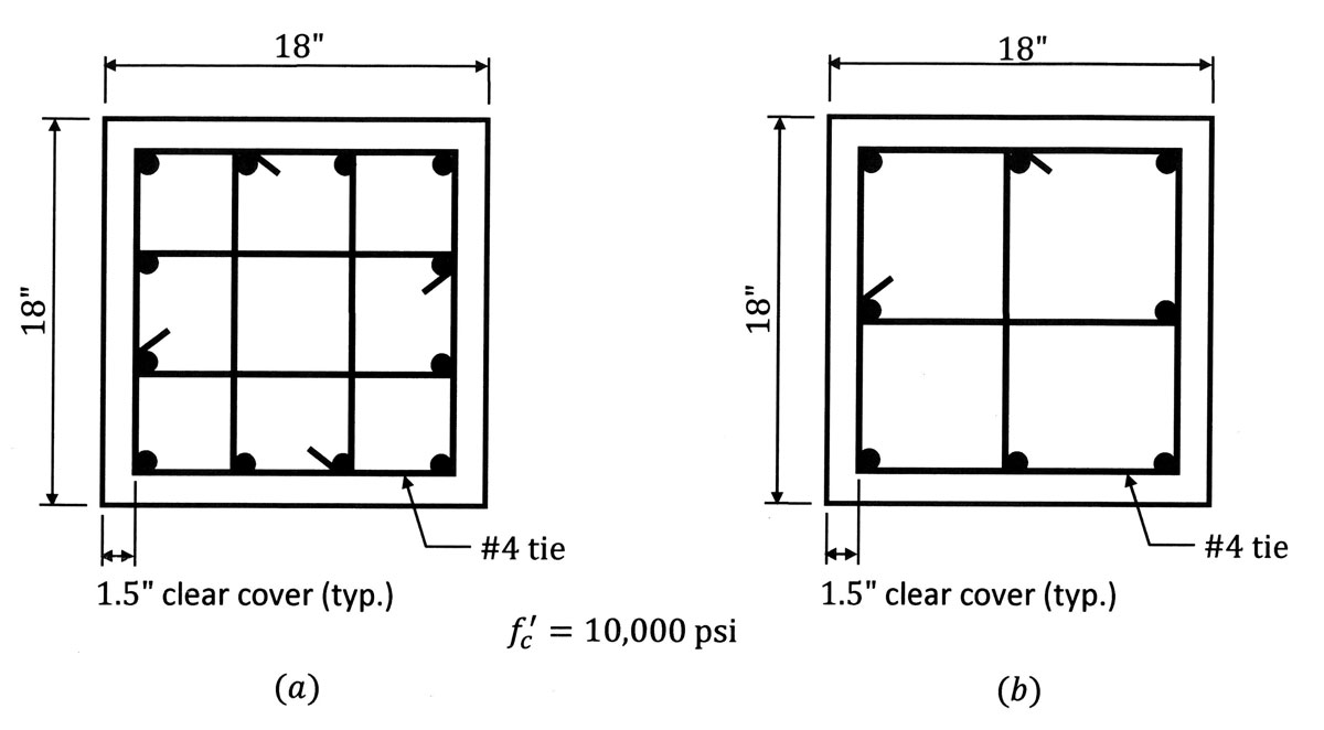
Figure 3. Reinforced concrete column. (a) Grade 60 reinforcement (b) Grade 80 reinforcement.
If Grade 80 bars were utilized instead (Figure 3b), 8- #9 bars would be required (ρg = 2.5%). Not only is the reinforcement ratio more reasonable, but the likelihood of congestion at the joints is also significantly reduced (the clear space between the bars is almost 5.5 inches). A comparison of the interaction diagrams of the column with different bar grades is given in Figure 4.
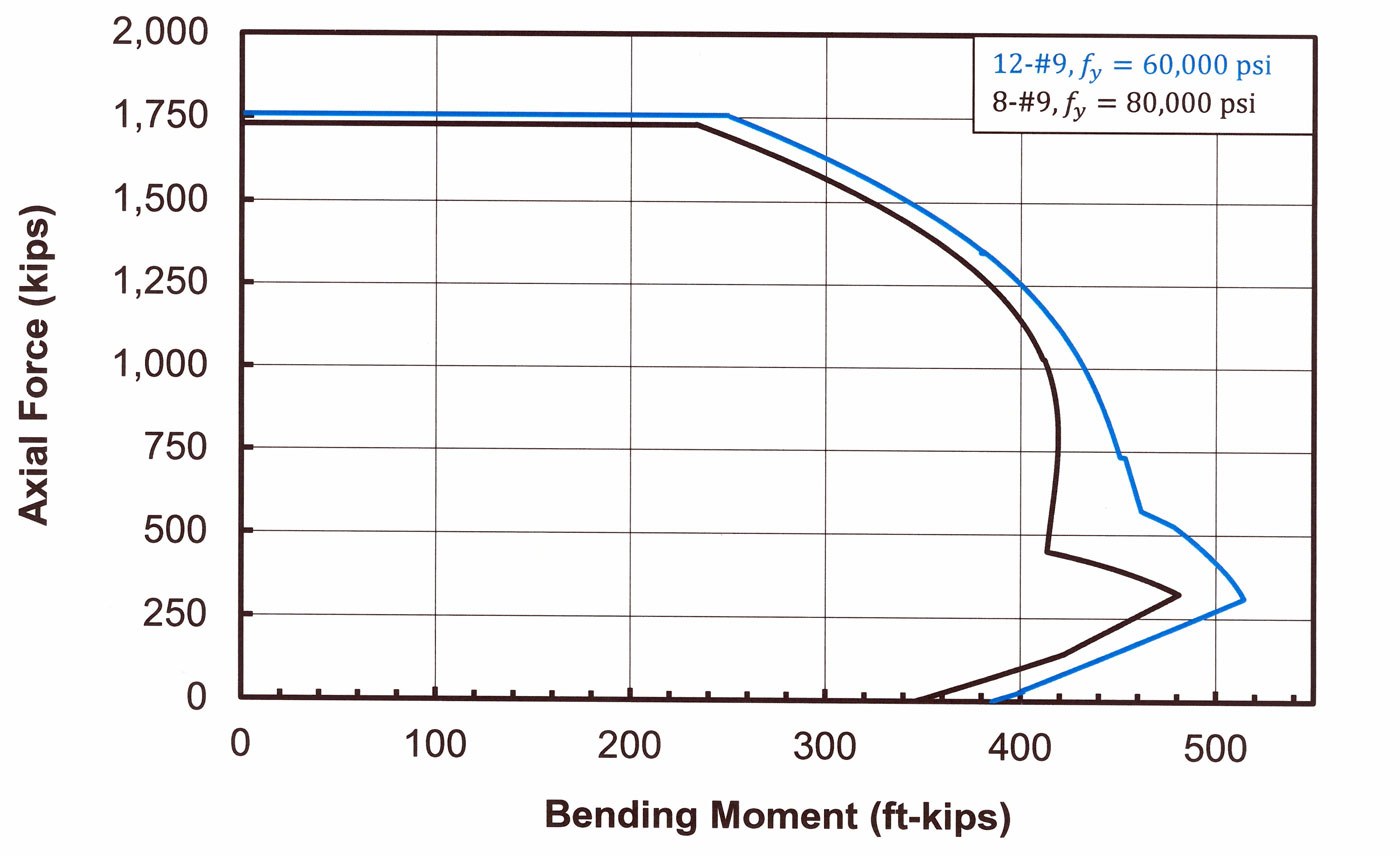
Figure 4. Interaction diagrams of the columns in Figure 5 with 12- #9 bars (Grade 60) and 8- #9 bars (Grade 80).
The cross-sectional area of a column with high-strength longitudinal bars may be smaller compared to one with Grade 60 bars, which could translate into more useable space. Figure 5 illustrates how the gross area of a column, Ag, decreases as a function of the yield strength, fy, for various concrete compressive strengths, f’c, and amounts of longitudinal reinforcement, Ast. It is clear from Figure 5 that combining high-strength reinforcement and high-strength concrete has the greatest impact on decreasing the required column area for a given percentage of longitudinal reinforcement, Ast/Ag. When reinforced concrete members are reduced in cross-section, it is always important to keep in mind the possibility of congestion issues that may accompany the size reduction.
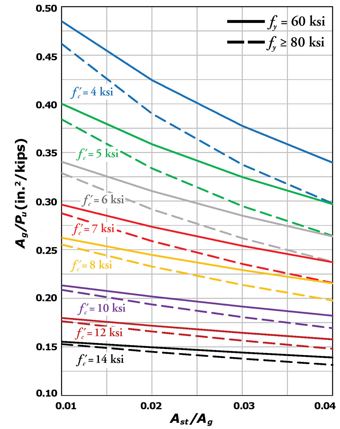
Figure 5. Required column area, Ag, as a function of reinforcing bar yield strength, fy, concrete compressive strength, f’c, and the amount of longitudinal reinforcement, Ast.
The Future of HSRB
It is anticipated that significant changes will be made to Table 20.2.2.4a in the 2019 edition of ACI 318 based on significant experimental data acquired for HSRB in both non-seismic and seismic applications. A public review edition of ACI 318-19 is now available, which highlights these changes.
The latest, most comprehensive information on HSRB can be obtained from the CRSI Technical Note, High-Strength Reinforcing Bars, which can be downloaded for free at www.crsi.org.■
References
ACI (American Concrete Institute). 2014. Building Code Requirements for Structural Concrete and Commentary. ACI 318-14, Farmington Hills, Michigan.
CRSI (Concrete Reinforcing Steel Institute). 2016. High-Strength Reinforcing Bars. ETN-M-8-16, Schaumburg, IL.