
Post-installed anchoring systems are very common, cost-effective methods for attaching both structural and non-structural elements to concrete base materials. Non-structural elements, such as fire sprinkler pipes, electrical conduit and cable trays, and heating, ventilating, and air conditioning (HVAC) equipment and ductwork are especially suited for post-installed anchor fastening. Building Integrated Modeling (BIM) has made cast-in anchors more common for non-structural elements hung from the ceiling, but post-installed fixations still dominate because mechanical and electrical locations can move after the concrete is cast.
While non-structural elements are not needed to support the main structure, their anchorage to concrete still requires the same level of safety as a design for a structural building element connection. Thus, it is still a requirement to design non-structural element connections to concrete using the anchor design provisions of Chapter 17 of ACI 318-14, Building Code Requirements for Structural Concrete and Commentary (ACI 318-14R). Non-structural elements will still have dead loads, live loads, and seismic loading conditions to consider.
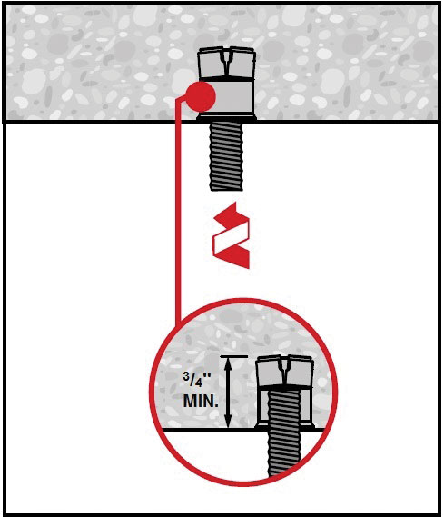
Example of a post-installed anchor with internal threads for non-structural hanging applications.
Many non-structural elements are hung from a concrete ceiling. Many concrete ceiling/floor systems consist of post-tension slabs or hollow-core precast concrete components. These concrete ceiling/floor systems can have prestressing steel cables that have ¾-inch cover from the underside of the concrete surface. This makes it difficult to attach items to the ceiling with a post-installed anchor due to the inability of the installer to locate the cables when drilling.
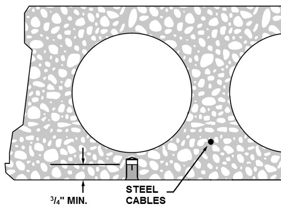
Traditional hollow core slab with prestressing steel cable.
To help contractors with attachments in concrete with prestressing steel cables and ¾-inch cover, post-installed anchor manufacturers have developed shallow embedment anchors that are intended to have ¾-inch drilled holes that will avoid the steel cables, no matter where the installer drills into the concrete ceiling.
Unfortunately, prior to October of 2017, the International Code Council Evaluation Service’s (ICC-ES) Acceptance Criteria (AC) for Mechanical Anchors in Concrete Elements (AC 193) did not permit testing and design of post-installed anchors with an embedment depth, hef, less than 1½ inches, except for redundant fastening designs which then permitted a 1-inch embedment depth. AC 193 is based on the American Concrete Institute’s (ACI) Qualification of Post-Installed Mechanical Anchors in Concrete and Commentary (ACI 355.2), which references ACI 318-11 Appendix D (now Chapter 17 in ACI 318-14). Redundant fastenings, per AC 193, are applications where multiple anchors support linear elements (i.e., sprinkler pipes) that will redistribute loads to neighboring anchors in case one anchor fails or exhibits excessive deflection. In all cases, this would restrict anchors with a ¾-inch embedment depth, even though the installer needed this shallow embedment to miss the steel cables in the concrete.
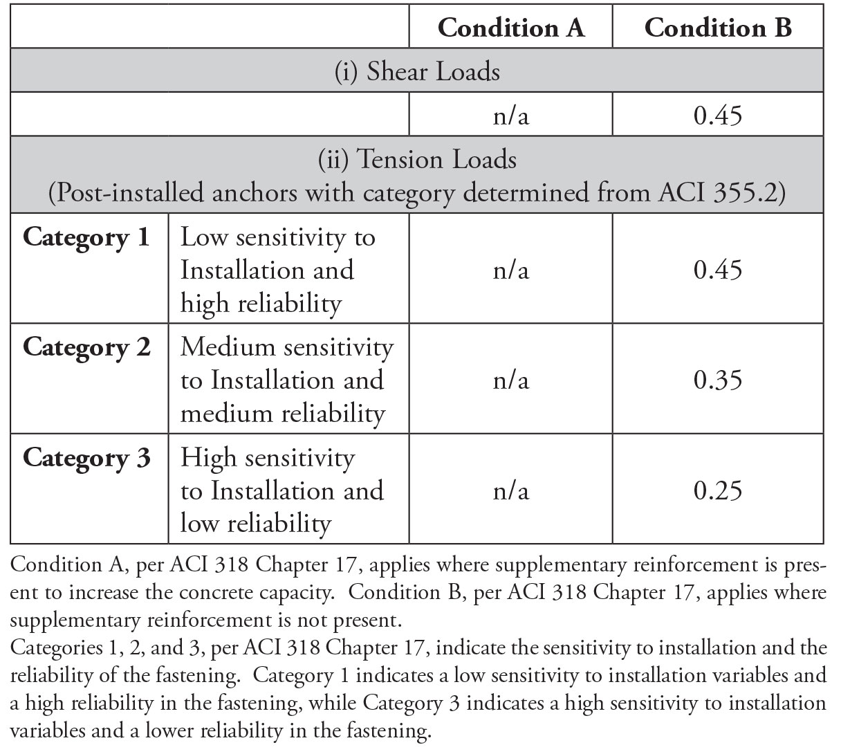
Table of strength reduction factors, as modified by AC193 for shallow anchors.
(anchor governed by concrete breakout, side-face blowout, pullout, or pryout strength)
Thus, in October of 2017, AC 193 was changed to include provisions to allow embedment depths from ¾-inch to 1½-inch (or 1-inch for redundant fastening). However, AC 193 did not just extend the minimum embedment depth range to ¾-inch. Anchors with a shallow embedment depth do not perform the same as anchors that have a 1½-inch embedment depth (and deeper). Thus, AC 193 incorporated five changes for anchors that have a shallow embedment depth:
- Near the surface, concrete does not have as consistent a performance for anchoring when compared with the interior of the concrete. This can be attributed to a higher concentration of the concrete paste near the surface, along with shrinkage cracking and exposure to environmental conditions. Thus, the concrete breakout model in ACI 318-14 Chapter 17 still applies, but the variability of the results has shown to be experimentally higher. AC 193 lowered the strength reduction factors indicated in ACI 318-14 Section 17.3.3(c) to the values shown in the Table.
- Similar to Item 1), experimental testing has shown that shallow anchors also perform worse when they are installed into the top surface of the concrete as opposed to the formed side of the concrete. An anchor installed in the non-formed side of the concrete could have as much as a 30% reduction in capacity when compared with an anchor installed in the formed side. The formed side will typically have a higher concentration of aggregate and the non-formed side will typically have a much higher concentration of concrete paste. Thus, without more testing, AC 193 is limiting the application to the formed side of a concrete member. This is satisfactory for most non-structural items that are installed in the ceiling.
- Similar to Items 1) and 2) above, experimentation has only been performed in dry, interior conditions. There are concerns that shallow anchors could have reductions in capacity since the environmental conditions affect the concrete surface. Thus, without more testing, AC 193 is limiting the application to dry, interior conditions. Again, this is acceptable for most non-structural items that are installed in an interior concrete ceiling.
- AC 193 is limiting the use of shallow anchors for non-structural applications. This means that the anchors should not be used for attaching a portion of the structural and load resisting system frames.
- Experimental tests have shown that shallow anchors have a concrete breakout cone angle less than 35 degrees. This means that, proportionally, the cone would be larger than the concrete breakout cone for deeper anchors. This also means that anchors need to be spaced farther apart from each other and the edge of the concrete to develop their full strength. AC 193 requires a minimum spacing of 4hef (4 x 0.75-inch = 3-inch spacing for a ¾-inch embedment anchor) and a minimum edge distance of 2hef (2 x 0.75 = 1.5-inch edge distance) for shallow anchors.
In summary, to address the needs of contractors who install post-installed anchors for non-structural building components in concrete members containing prestressing steel cables that may have a ¾-inch cover, ICC-ES AC 193 was revised to permit a shallow embedment depth no less than ¾-inch. This gives installers a high level of flexibility while still maintaining a high level of safety and reliability.■