
Part 1: Codes and Detailing
It is relatively common for light wood-frame commercial and multi-family buildings to include shaft walls made from other materials. However, with an increase in wood construction nationwide, many designers and contractors have come to realize that wood-frame shaft walls are a code-compliant means of reducing costs and shortening construction schedules.
Part 1 of a two-part series, this article provides an overview of building code considerations and detailing. Part 2 will examine fire design requirements, construction constraints, and other potential differences associated with specific applications such as stairs, elevators, and MEP shafts.
Fire Barrier Construction
Shaft enclosures are specifically addressed in Section 713 of the 2015 International Building Code (IBC). However, because shaft enclosure walls are to be constructed as fire barriers per Section 713.2, many shaft wall requirements directly reference provisions on fire barriers found in Section 707.
Provisions addressing materials permitted in shaft wall construction are given in both the shaft enclosures section (713.3) and fire barriers section (707.2). These sections state that fire barriers can be constructed of any material permitted by the building’s type of construction. This means that light-frame wood construction or mass timber may be used for shaft wall construction in Construction Types III, IV, and V per the construction type definitions in IBC Section 602. The one exception is when shaft walls in Type III or IV Construction are also exterior walls. This requires that the exterior/shaft walls be fire-retardant-treated wood framing or non-combustible framing.
Per IBC Section 713.4, shaft enclosures are required to have a fire-resistance rating of not less than 2 hours when connecting four or more stories. A fire-resistance rating of not less than 1 hour is required for shaft enclosures connecting less than four stories.
Continuity
IBC Section 707.5 states the requirements for fire protection continuity of fire barriers. It requires that fire barriers “extend from the top of the foundation or floor/ceiling assembly below to the underside of the floor or roof sheathing, slab or deck above and shall be securely attached thereto. Such fire barriers shall be continuous through concealed space, such as the space above a suspended ceiling.” This is one of the main distinctions between a fire barrier and fire partition. A fire partition (for example, a corridor wall) is permitted to terminate at the underside of a fire-resistance-rated floor/ceiling or roof/ceiling assembly while a fire barrier is required to extend up to the underside of the floor/roof sheathing.
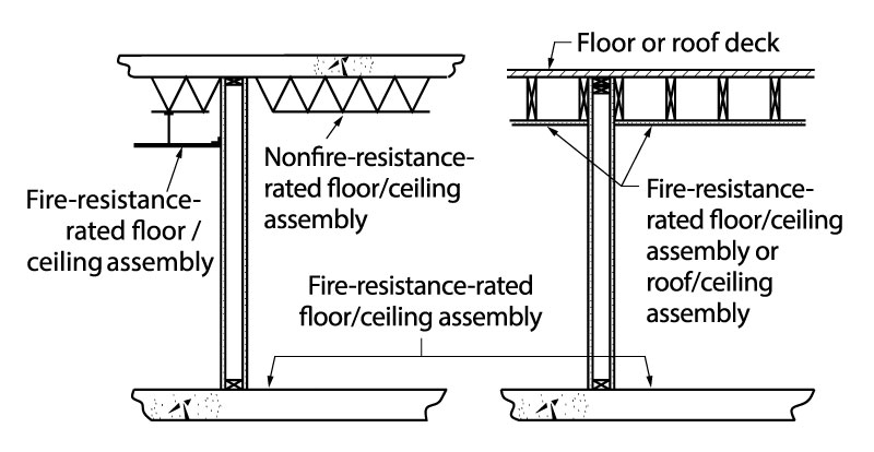
Figure 1. IBC Commentary Figure 707.5 – continuity of fire barriers.
This continuity condition is depicted in the code commentary in a simplistic form where the shaft wall runs parallel to the floor framing (Figure 1). However, in platform-frame buildings, there are usually shaft walls that directly support perpendicular framing elements. It is essential to understand that continuity of the assembly can be maintained even in these scenarios.
Having a single fire-resistance-rated assembly running from the bottom to the top of a shaft enclosure with no interruptions, such as a masonry wall, is considered by some to be the clearest path to meeting this requirement. However, given the potential costs and structural challenges associated with integrating masonry shaft walls in wood-frame buildings, wood-frame shaft walls are becoming increasingly popular. The requirement is for continuity, but this does not dictate the use of only one assembly. Since fire protection continuity does not equate to wall framing continuity, using means of fire protection other than the tested wall assembly in the depth of the framed floor can be an effective way of providing the required continuity.
Ultimately, the detail used will reflect what the building official accepts in terms of fire protection continuity of the shaft wall’s required fire-resistance rating. In varying degrees (depending on the detail), the shaft wall will need to be interrupted to attach the adjacent floor framing and floor sheathing. The methods used at this floor-to-wall intersection will also depend somewhat on the floor framing configuration. See “Detailing Floor-to-Wall Intersections” below for examples of ways designers have detailed this condition.
Supporting Construction
IBC Section 707.5.1 requires that “The supporting construction for a fire barrier shall be protected to afford the required fire-resistance rating of the fire barrier supported.” In the scenario where a fire barrier wall line is vertically discontinuous (e.g., fully stopped at a floor and does not continue below that floor), it is clear that the floor is indeed a direct support. For example, if the floor were to fail after 1 hour of fire exposure, the wall above could not continue to contain the fire for 2 hours. However, in the condition where a fire barrier wall is supported directly below a floor by another fire barrier, the fire endurance of the floor assembly that lies between the two fire barrier assemblies would not affect the ability of the fire barrier above and below to perform for the full duration of their intended fire resistance. In this scenario, maintaining the code’s continuity requirements for the wall through the floor depth should also satisfy the supporting construction requirements.
Structural Shaft Wall Penetrations
It is often necessary to penetrate a shaft wall with a structural member such as floor sheathing, a landing beam, or floor joists (Figure 2). The allowance for these penetrations comes from IBC Section 713.8, which states that “Penetrations in a shaft enclosure shall be protected in accordance with Section 714 as required for fire barriers. Structural elements, such as beams or joists, where protected in accordance with Section 714 shall be permitted to penetrate a shaft enclosure.”
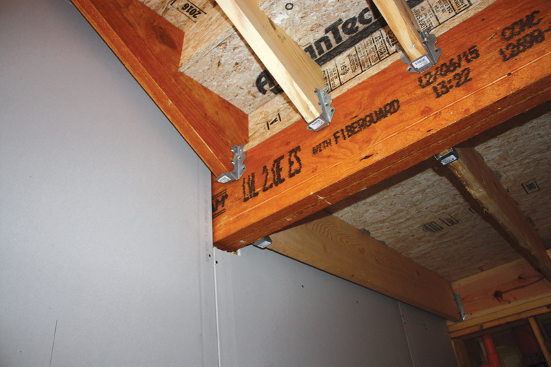
Figure 2. Stair landing beam shaft wall structural penetration prior to fire caulk installation.
IBC Section 714.3 requires that penetrations into or through shaft walls comply with Sections 714.3.1 through 714.3.3. Section 714.3.2 requires that either:
- Penetrations shall be installed as tested in an approved fire-resistance-rated assembly (i.e., incorporated during the conduct of an ASTM E119 test of the wall or floor assembly, per Section 714.3.1.1) or, more commonly,
- Protected by an approved penetration firestop system installed as tested in accordance with ASTM E 814 or UL 1479, with an F (flame) rating of not less than the required fire-resistance rating of the wall penetrated (per Section 714.3.1.2).
As noted, the option given in IBC Section 714.3.1.2 is the most common approach and typically involves the use of a tested, approved firestop system to seal around structural penetrations in shaft walls.
Assemblies & Intersections
The first step in detailing shaft wall construction is to select the rated wall assembly that is appropriate for the application. The assembly type chosen will depend on several application-specific constraints, including space available for the wall assembly, accessibility to finish gypsum wallboard, the height of the shaft, acoustic needs, and construction efficiency. In some cases, the floor-to-wall intersection detailing necessary for plan approval may affect the type of wall assembly chosen.
As noted, per IBC Section 713.4, shaft enclosures are required to have a fire-resistance rating of not less than 2 hours when connecting four or more stories. A fire-resistance rating of not less than 1 hour is required for shaft enclosures connecting less than four stories. See Figure 3 for various options.
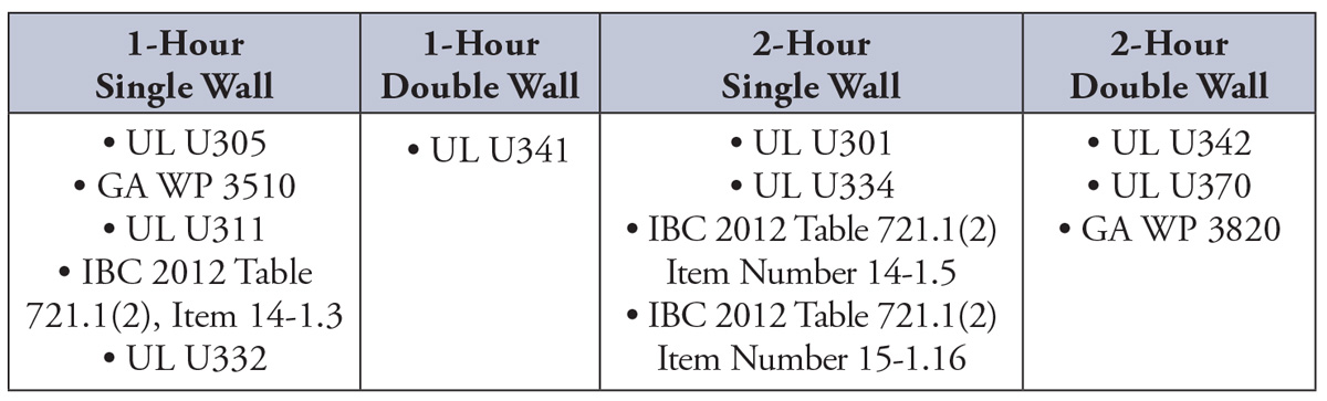
Figure 3. Options for fire resistance rated, wood frame wall assemblies that could be useful for shafts.
Double wall options provide opportunities for higher acoustically-rated assemblies and/or a way to decouple membrane continuity and structural support. In particular, better acoustical performance may be desired when shaft walls separate the shaft from a residential unit or other occupied space. For more information on acoustical performance of light-frame wood walls, see the WoodWorks publication, Acoustical Considerations for Mixed-Use Wood-Frame Buildings.
Some designers also utilize shaftliner panels. Shaftliner panels are typically thicker than a normal gypsum panel (1-inch-thick is common) and come in sizes that can be installed easily between CH-, CT-, or H-studs. These studs are cold-formed steel sections that hold the shaftliner panels together and eliminate the need for gypsum panel joint finishing. Some assemblies are tested with a supporting wood structure (UL U375), and others are not (GA ASW 1000). This is an important distinction to make when discussing continuity and structural support. Even if included in the tested wall assembly, the wood walls are usually assumed not to be providing part of the wall’s fire-resistance rating. The 1-hour or 2-hour rating can typically be accomplished solely with the shaftliner panels. If tested with a supporting wood structure, only lateral bracing of the shaftliner panels is assumed. The weight of the panels is carried through the panels to the foundation unless specifically detailed otherwise.
Assemblies such as UL U336 have an option for a single wood-frame wall supporting a double shaftliner gypsum membrane. A second wood wall could be used on the other side of the double gypsum membrane to support floor framing (i.e., stair and landing framing). Alternatively, only one wood wall could be used (on the non-shaft side), and the gypsum membrane could face the inside of the shaft. This allows structural support of the main floor and roof framing to occur without penetrating the membrane. See Figure 4 for options.

Figure 4. Shaftliner panels, 1- and 2- hour ratings.
Height Limitations
A common question that arises when utilizing shaftliner panels is that of limiting heights, both floor-to-floor and overall. Many shaftliner manufacturers publish maximum floor-to-floor heights and/or maximum system height limitations. An example is assembly UL U375 which allows a total system height up to 66 feet but requires different H-stud clip angle spacing depending on total system height.
The limiting height of these systems is due to the fact that they are designed to be non-load bearing walls. As the self-weight of the wall assembly accumulates throughout the height of the wall, axial stresses on the non-load bearing steel studs could increase to the point where they become inadequate, creating a need for a limiting height. Also, these walls are generally designed for a minimal internal horizontal pressure, typically about 5 pounds per square foot (psf). The prescriptive allowable height tables published by the manufacturer can potentially be increased when the project’s structural engineer analyzes the cold-formed steel stud sections to determine their capacity against the project’s actual loading conditions. Most CH-stud manufacturers provide structural section properties for their products that can be used for this purpose. Most of these sections are available in 25-gauge and 20-gauge options, so using the slightly thicker 20-gauge option might help in making a wall height work. Additionally, 4-inch-deep and 6-inch-deep CH-stud sections are typically available and would have higher load capacities than the standard 2½-inch-deep option. The wall stud and system manufacturer should be consulted for input on options that exceed their published allowable height tables.
If a proposed shaft wall using shaftliner panels does not meet the total system height limitations, supporting the mass of the wall at intermittent heights off the adjacent floor structure is an option. Maintaining the wall’s fire-resistance rating at the support attachment locations is a primary design objective if choosing this option.
Detailing Floor-to-Wall Intersections
Once the typical wall assembly for the shaft has been selected, the detail at the floor-to-shaft intersection should be addressed. The look of this detail will depend on the floor framing type and bearing condition.
One method used by designers to demonstrate continuity of the shaft wall through the floor cavity is having the wall gypsum stop at the underside of the floor framing and installing wood blocking in the floor cavity. The concept is that approximately every 1.5 inches of wood blocking thickness provides 1 hour of fire protection. This rationale is codified through IBC Section 722.1, which references Chapter 16 of the American Wood Council’s National Design Specification® (NDS®) for Wood Construction for calculated fire resistance of exposed wood members. NDS Chapter 16 indicates that the nominal char rate of a number of wood products, including solid sawn lumber and structural composite lumber, is 1.5 inches per hour. See Figure 5 for an example of this detail.
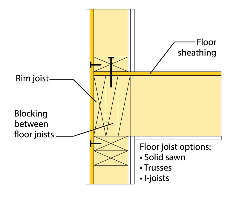
Figure 5: Floor-to-shaft wall intersection detail with blocking between floor joists.
Another option would be to extend the wall gypsum on the floor side of the shaft wall up to the underside of the floor/roof sheathing between the floor/roof joists. This would require interruptions of the gypsum at the joists. See Figure 6 for an example of this detail. The joist is merely a structural penetration, which is allowed in shaft wall construction as noted above when protected according to Section 714.
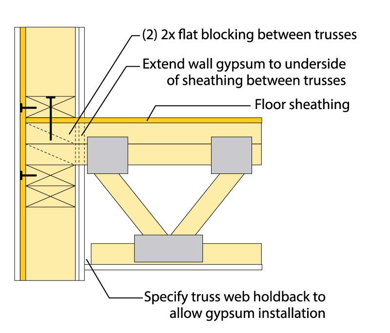
Figure 6: Floor to shaft wall intersection detail with gypsum extending to the underside of sheathing between trusses.
A third option would be to install a floor beam parallel to and just inboard of the shaft. This beam would be used to support all of the framing perpendicular to the shaft wall such that the only element penetrating the shaft wall is the floor sheathing. This option is only feasible if the length of the shaft wall is such that a reasonable beam size can still be used. Walls or beams parallel to and just beyond the ends of the shaft are used to support the ends of the beam mentioned above.
A final option would be to run the gypsum continuously behind the floor joists up to the underside of the floor/roof sheathing. The joists would be hung from the wall with a top flange hanger capable of spanning over one or two layers of gypsum.▪
This article is excerpted from the WoodWorks paper, Shaft Wall Solutions for Wood-Frame Buildings, available at www.woodworks.org.