
Part 2: Investigation, Repair, and Rehabilitation
Part 1 of this 2-part series (STRUCTURE, June 2018) addressed structural behavior and assessment methods. Part 2 focuses on analysis and repair options.
Bowstring trusses were a popular solution for structurally supporting roofs from the 1900s through the 1950s, especially in buildings where large, open spans were desired (manufacturing facilities, garages, warehouses, among others). Many buildings with this type of roof support are still in service today; given their age and inherent vulnerability (e.g., to environmental, load, and other factors), their adequacy and reliability have become a common reason for concern. This article focuses on potential retrofit options for bowstring trusses that have been identified, through structural assessment (see Part 1 of this series), to be in need of repair.
Analysis
After information on existing conditions has been collected in the field, structural analysis is performed to evaluate the behavior and determine the structural adequacy of the trusses. The member service load demands, determined through structural analysis or modeling (based on the current or planned use and codes), are compared to the allowable service level capacities for each member and connection in the truss. The calculated structural demand-to-capacity ratios for each truss component then allows the engineers to assess the adequacy of the truss to withstand the requisite building-code-prescribed loads. Recurring typical considerations associated with the analysis and design-check processes are discussed below.
Changes in Design Snow Loads
Until approximately the 1970s, building codes did not include consideration of drifting or unbalanced snow loads. Nevertheless, significant additional loads can result from the accumulation of snow against parapet walls, adjacent buildings, added mechanical equipment, and modifications to the roof layout (e.g., the formation of valleys). These conditions result in member forces that are different from those considered in the original design. Specifically, an increase in bending moments and/or axial forces in localized areas of both top and bottom chords, as well as an increase in axial loads in the web members, can be expected.
Changes in Design Dead and Live Load
Buildings may undergo several renovations or other modifications throughout their life-span. Often, changes such as reroofing, the addition of mechanical equipment (over the roof or hung from the trusses), or addition of ceiling finishes happen without the supervision of a registered professional engineer. These changes can result in increased uniformly-distributed loads and/or in new load-patterned conditions that were not considered in the original design.
Boundary Conditions
The accuracy of results in structural analyses depends, among other things, on proper assumptions and interpretation of the boundary conditions. The calculated tensile force in the bottom chord of the truss is particularly sensitive to these assumptions. For example, a pin-roller truss model (horizontal movement is restrained at one end only) would generally yield the highest tensile force in the bottom chord, whereas a pin-pin truss model (horizontal movement restrained at both ends) would yield the lowest tensile force in the bottom chord. The authors have found that actual field conditions typically do not warrant selection of a pin-pin model. If necessary, the design tensile force in the bottom chord can be limited by considering the actual lateral stiffness of truss support elements (e.g., columns and kickers, masonry piers, walls, etc.) in the analysis. If such consideration is made, the adequacy of the support elements to withstand the lateral loads imposed by the truss should be verified.
Top Chord Composite Action
The top chord is a truss member typically subjected to compressive and bending stresses. As such, the ability of the laminations, if present, to behave compositely (act as one section) may substantially affect the overall truss capacity. If composite action cannot be developed, the ability of the top chord to withstand the design loads may be compromised. This behavior should be investigated when determining the allowable capacity of the top chord. Any analysis that relies on partial or full composite action of the top chord laminations requires an evaluation of the adequacy of the connection between laminations to transfer the horizontal shear flow. Different methods to connect the top chord laminations exist in practice. In a lattice truss, all laminations are typically nailed to each of the closely-spaced web members. Trusses with discrete web members rely on bolts through the depth of the top chord (through bolts) to transfer the forces; one through bolt is typically found at each side of the panel points (Figure 1). Finally, the laminations may be glued together (glue-laminated construction); however, glue-laminated construction was not standardized nor was it used in the production of bowstring trusses prior to the 1930s.
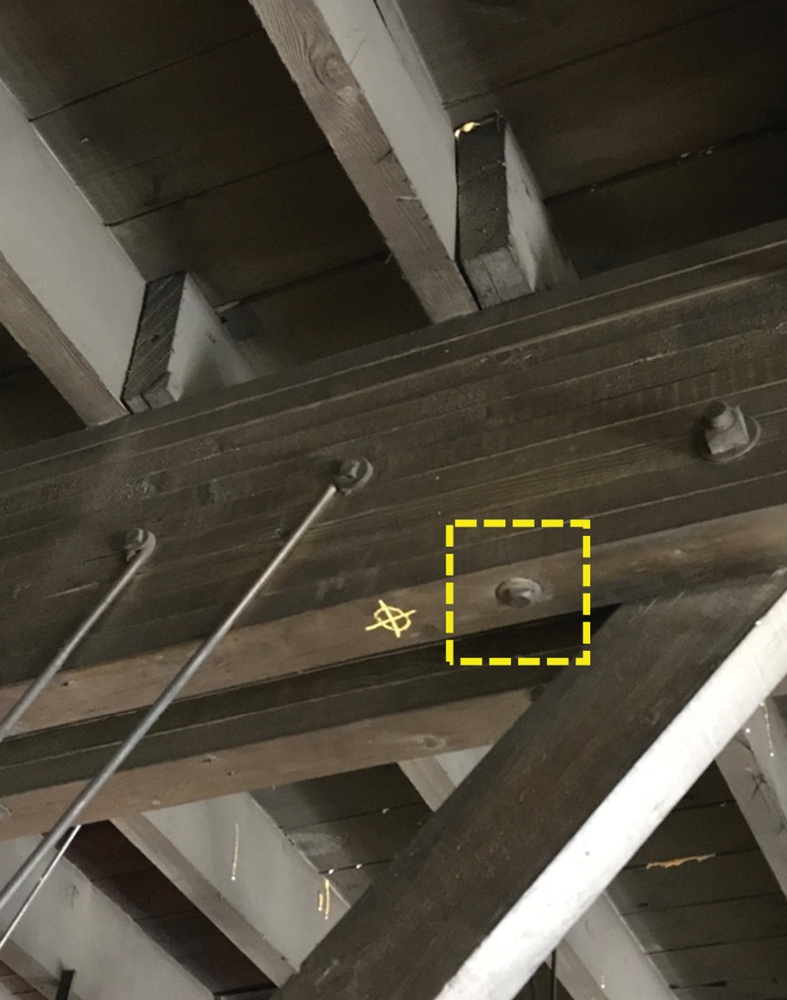
Figure 1. Through-bolt inserted through the depth of the top chord of a bowstring truss
Allowable Wood Design Values
There are two methods for selecting allowable wood design values: 1) stress grading rules in combination with reference design values published by the National Design Specification® for Wood Construction (NDS®) or other local ordinances, or 2) by applying the visual stress grading method, in accordance with ASTM D245, Standard Practice for Establishing Structural Grades and Related Allowable Properties for Visually Graded Lumber, in conjunction with published clear wood strength values. Typically, the first method provides more conservative values than the second one. When applying the first method, it is important to recognize which edition of the NDS standard includes reference design values that are most applicable to the investigation at hand. For example, prior to the 1960s, the allowable tensile stress parallel to grain was determined from bending tests on small, clear wood samples. In the 1960s, tensile tests on full-size lumber pieces (with natural imperfections) revealed that the allowable tensile stress was significantly lower than that determined from bending tests. Currently, reference design values for tension parallel to grain are approximately at 60% of the reference values for bending. Care should be taken to avoid using reference wood design values determined based on obsolete knowledge. Care should also be exercised to avoid the use of reference design values that are not representative of wood produced at the time the trusses in question were constructed. When using the visual stress grading methodology, careful consideration should be given to the method used to calculate the allowable design values, and to accurately assess the representativeness of the limited size of members sampled (e.g., 95% probability of exceedance method).
Typical Repair Options
When structural analysis reveals that some components of the truss are inadequate to withstand the building-code-prescribed loads, repair/strengthening is warranted. Repair strategies can vary depending on the level of overstress, cost, access, level of current load on the trusses, etc. Different repair/strengthening details that the authors have considered in their past projects with bowstring trusses are listed below.
Design Loads – When drift is the controlling condition in the calculation of design snow loads, installation of sacrificial roof framing over the existing roof may be used to preclude formation of a snow drift. This adds dead load to the trusses, but it may still result in lower overall design loads.
Top Chord – Partial or full composite action among the laminations can be achieved through installation of (additional) lag screws (or proprietary screws) at sufficient spacing and edge distances, which would enhance the shear flow through the section depth. Careful considerations should be made with respect to access, the location of splices of single laminations, ease of drilling through all laminations, and overall ease of installation.
Web Members – Overstressed or distressed diagonal members can be repaired by installing new “sister” members bolted (or nailed) to the existing members. In some instances, replacement of web members is warranted or easier.
Bottom Chord – The bottom chord can be retrofitted by installing steel tension rods along the span of the truss. This can be accompanied by steel brackets at the ends of the truss, designed to transfer the force from the top chord to the new steel rods (Figure 2). Alternatively, installation of new “sister” members bolted (or nailed) to the existing members may be considered.
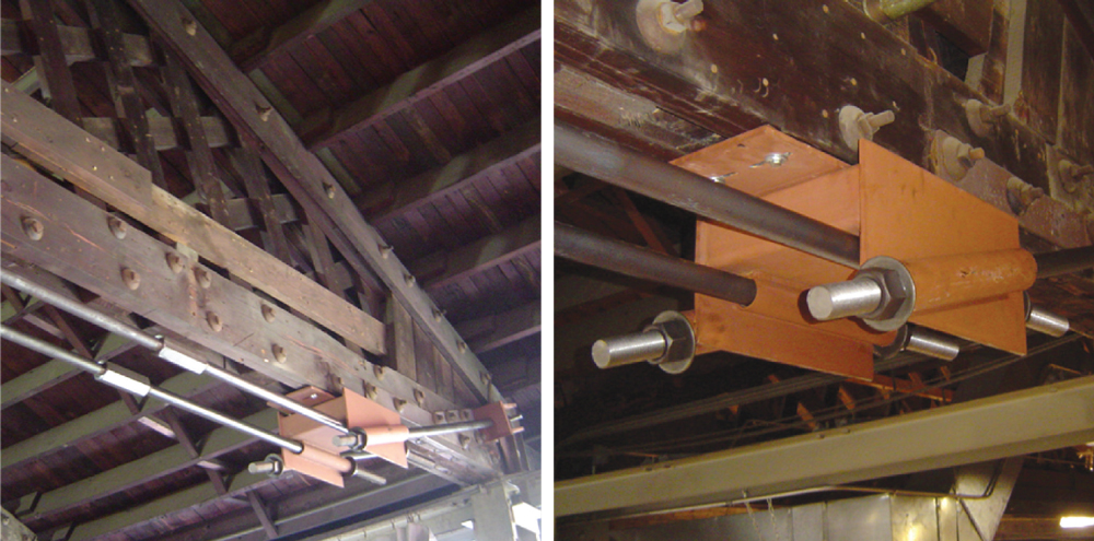
Figure 2. Bottom chord of bowstring truss retrofitted by installing steel tension rods along the span of the truss (left). The steel bracket at the end of the truss (right) transfers the force from the top chord to the new steel rods.
Bolted Connections – Inadequate bolted connections can be reinforced by installing supplemental steel plates with proper consideration of boundary conditions (e.g., spacing, end, and edge distances of bolts) and compatibility (differential hygrometric behavior between steel and wood).
Bearing Ends – When decay associated with moisture intrusion is found at the ends of the trusses and the remaining, sound bearing areas are inadequate to transfer loads, repair may include installation of supplemental (e.g., steel) framing support tight to the underside of the bottom chord. This can be a seat connected to the existing column, pier, or wall. If the decay is driven by excessive moisture, the U-shaped steel straps at the ends of the truss may also be severely corroded. Depending on the degree of corrosion and decay, reinforcement of the steel strap may also be required through installation of additional steel plates and bolts.
Conclusions
To achieve long-lasting performance, to increase the expected service life, and to avoid chronic, recurring structural problems, the repair strategy for bowstring trusses, as for any other structure, must focus on, consider, and eliminate the underlying sources of identified issues or problems. For example, rather than just strengthening the decayed or corroded elements, the source of moisture should also be eliminated (through repairing leaks, installing waterproofing and flashing details at masonry piers, etc.). Typical repair approaches and methodologies include installation of sacrificial framing to preclude formation of a snow drift, establishing full composite action of the top chord, sistering members, installing steel tension rods in the bottom chord, and installation of seats and additional steel plates at the bearing ends.▪
References
Kidder, F. E., & Parker, H. (1936). Kidder-Parker architects’ and builders’ handbooks.
Herzog, T., Natterer, J., Schweitzer, R., Volz, M., & Winter, W. (2004). Timber construction manual. Walter de Gruyter.
Galligan, W. L., Gerhards, C. C., & Ethington, R. L. (1979). Evolution of Tensile Design Stresses for Lumber (No. FSGTR-FPL-28). Forest Products Lab, Madison Wi.
American Wood Council. (2005). National Design Specification (NDS) Supplement: Design values for wood construction.