
Determining Components and Cladding Roof Design Pressures
Component and cladding (C&C) roof pressures changed significantly in ASCE 7-16, Minimum Design Loads and Associated Criteria for Buildings and Other Structures. For flat roofs, the corner zones changed to an ‘L’ shape with zone widths based on the mean roof height and an additional edge zone was added. Additional edge zones have also been added for gable and hip roofs. These changes are illustrated in Figure 1. For gable and hip roofs, in addition to the changes in the number of the roof wind pressure zones, the smallest and largest effective wind areas (EWA) have changed. And, the largest negative external pressure coefficients have increased on most roof zones. Hip roofs have several additional configurations that were not available in previous editions of ASCE 7. The coefficients for hip roofs are based on the h/B ratio (mean roof height to the building width ratio) and, for roofs with slopes from 27° to 45°, the coefficients are a function of the slope.
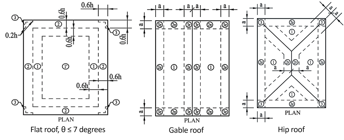
Figure 1. Examples of ASCE 7-16 roof wind pressure zones for flat, gable, and hip roofs. Printed with permission from ASCE.
The significance of these changes is the increase in pressures that must be resisted by roof construction elements subject to component and cladding wind loads including but not limited to roof framing and connections, sheathing, and attachment of sheathing to framing. To resist these increased pressures, it is expected that roof designs will incorporate changes such as more fasteners, larger fasteners, closer spacing of fasteners, thicker sheathing, increased framing member size, more closely spaced roof framing, or a change in attachment method (e.g., change smooth shank nails to ring shank nails or screws). An example of these wind pressure increases created by the increase in roof pressure coefficients is illustrated in Table 1. This Table compares results between ASCE 7-10 and ASCE 7-16 based on 140 mph wind speeds in Exposure C using the smallest EWA at 15-foot mean roof height in Zone 2. Pressure increases vary by zone and roof slope. In some cases not shown in Table 1, such as for Zone 1, the revised coefficients produce an approximate doubling of roof pressures.
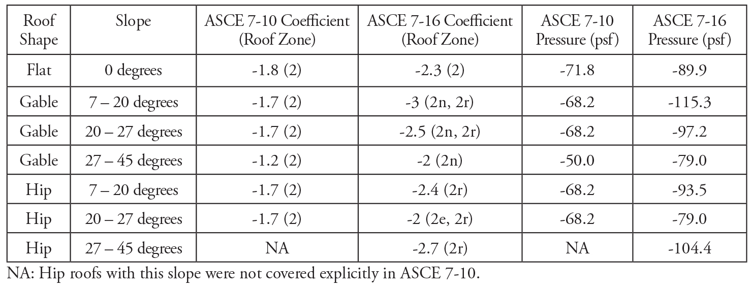
Table 1. Comparative C&C negative pressures, 140 mph, 15-foot mean roof height, Exposure C.
C&C Wind Pressure Comparisons
There are several compensating changes in other wind design parameters that reduce these design pressures in many parts of the country. These changes are:
- Wind speed maps west of the hurricane-prone region have changed across the country. Wind speeds in the Midwest and west coast are 5-15 mph lower in ASCE 7-16 than in ASCE 7-10.
- The elevation/exposure coefficient, Kz, has been reduced for C&C pressures for Exposure B buildings up to a height of 30 feet. Since most buildings are in Exposure B, this reduction in Kz will affect many structures. Table 26.10-1 in ASCE 7-16 provides the Kz coefficients. The Kz coefficient used in ASCE 7-10 for C&C was listed in Chapter 30 for use with C&C design. Now that the Kz coefficient is the same for both the Main Wind-Force Resisting System (MWFRS) and C&C, that table has been moved to Chapter 26.
- There is an elevation factor, Ke, that reduces the velocity pressure q for a site elevation above 1000 feet. This reduced pressure considers the lower air density at higher elevations; thus this factor modifies the 0.00256 multiplier used in the velocity pressure equation. Over 20 states have a mean elevation over 1000 feet, so a significant part of the country could take advantage of the reduced velocity pressure created by the new Ke factor. This factor is listed in Table 26.9-1 in ASCE 7-16.
Table 2 illustrates the Zone 2 (20- to 27-degree slope) C&C pressures for ASCE 7-10 compared to the pressures developed in accordance with ASCE 7-16. The comparison is for 10 different cities in the US with the modifiers for Exposure B taken at 15 feet above grade, location elevation factor, smallest applicable EWA, and reduced wind speeds from new maps applied from ASCE 7-16 as appropriate.
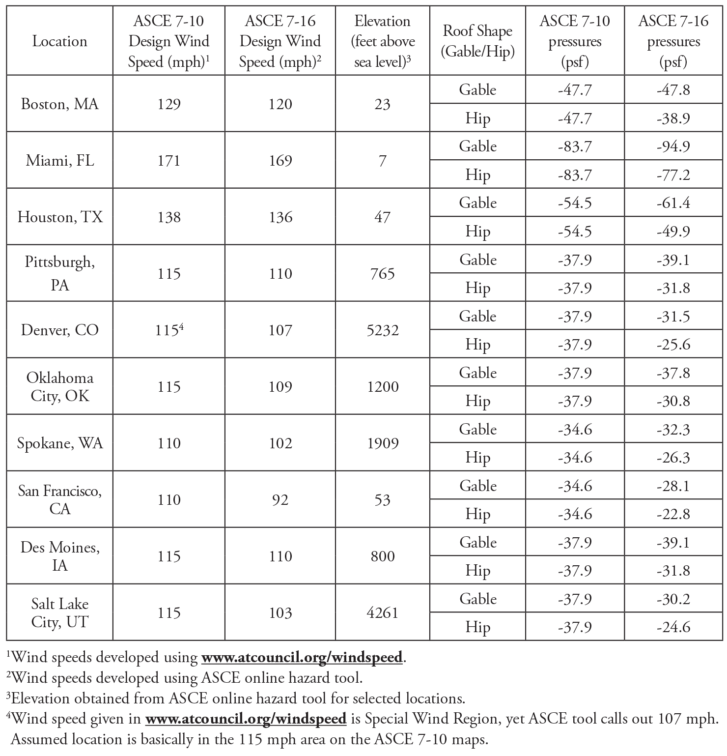
Table 2. Comparative C&C negative pressures for select locations, 15-foot mean roof height, Exposure B, Zone 2 or 2r (20- to 27-degree slope).
As illustrated in Table 2, the design wind pressures can be reduced depending on location elevation, wind speed at the site location, exposure and height above grade, and roof shape. Wind pressures have increased in the hurricane-prone regions where Exposure C is prevalent and wind speeds are greater. The added pressure zones and EWA changes have complicated the application of these changes for the user.
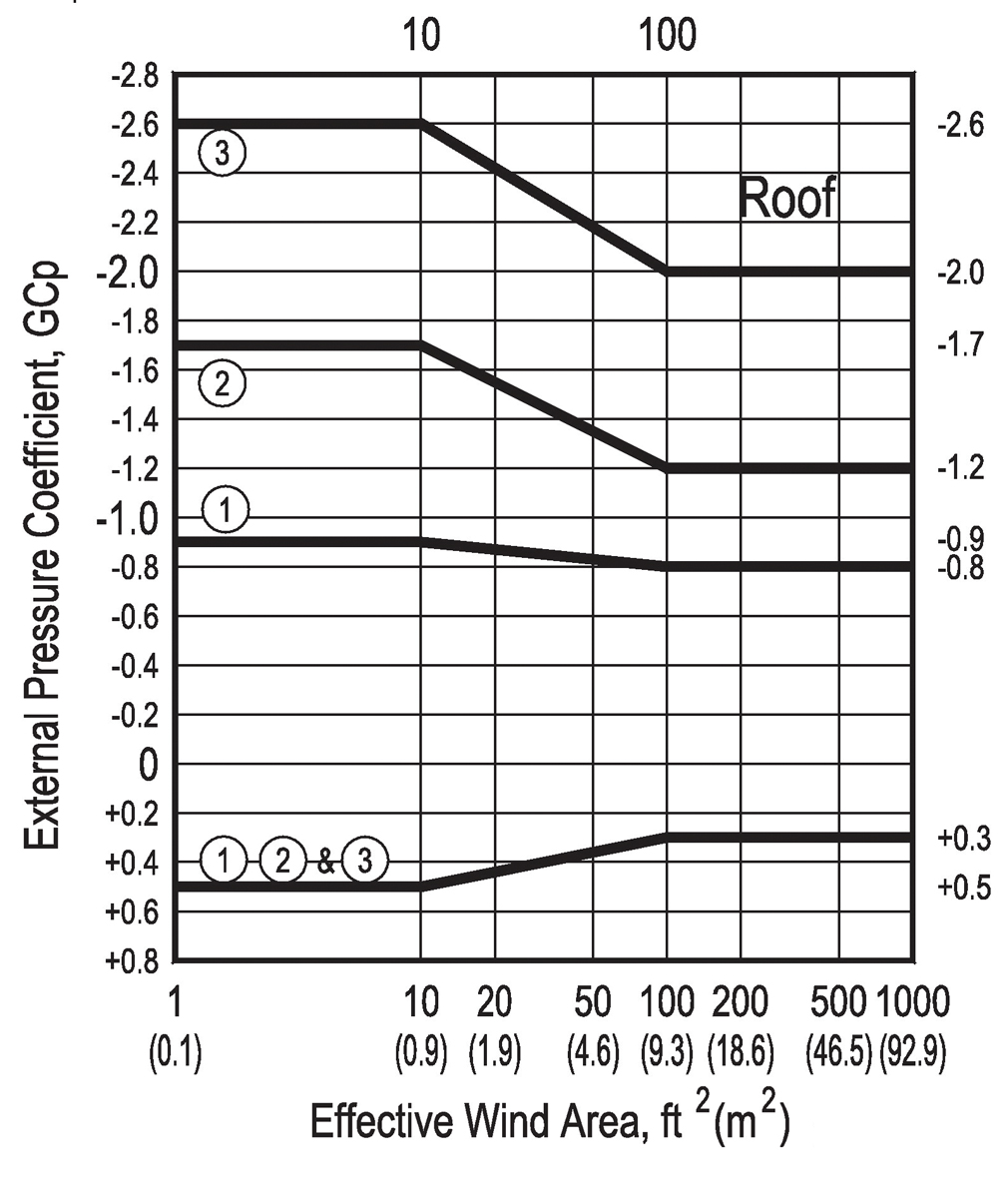
Figure 2. ASCE 7-10 Gable Roof Coefficients 20- to 27-degree slope. Printed with permission from ASCE.
Figures 2 and 3 illustrate the changes in the number of zones as well as the increases in the roof zone coefficients from ASCE 7-10 to 7-16 for gable roofs. Designers are encouraged to carefully study the impacts these changes have on their own designs or in their standard design practices. The reduced pressures for hip roofs in ASCE 7-16 are finally able to be demonstrated in Table 2; the design premise for hip roofs has always suggested this roof shape has lower wind pressures, but the C&C tables used for design did not support that premise until this new ASCE 7-16 edition. There is interest at the ASCE 7 Wind Load Task Committee in studying ways to make these changes simpler and reduce possible confusion in the application of C&C provisions for the ASCE 7-22 cycle.
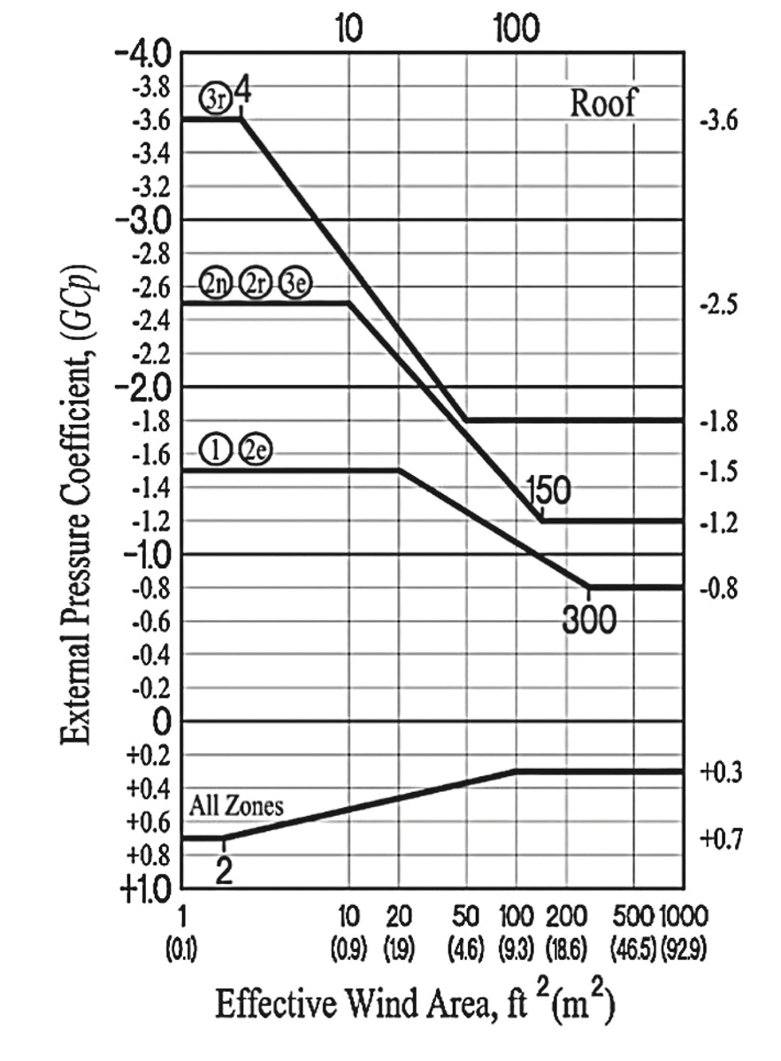
Figure 3. ASCE 7-16 Gable Roof Coefficients 20- to 27-degree slope. Printed with permission from ASCE.
ASCE 7-16 Wind Loads and the Model Codes
ASCE 7-16 is referenced in the 2018 International Building Code (IBC) for wind loads. In the 2018 International Residential Code (IRC), ASCE 7-16 is referenced as one of several options where wind design is required in accordance with IRC. Other permitted options based on ASCE 7-16 include the 2018 IBC and the 2018 Wood Frame Construction Manual (WFCM). Other permissible wind design options which do not reflect updated wind loads in accordance with ASCE 7-16 include ICC-600 and AISI S230.
For more information on the significance of ASCE 7-16 wind load provisions on wind design for wood construction, see Changes to the 2018 Wood Frame Construction Manual (Codes and Standards, STRUCTURE, June 2018). As described above, revised roof construction details to accommodate increased roof wind pressures include revised fastener schedules for roof sheathing attachment, revised sheathing thickness requirements, and framing and connection details for overhangs at roof edge zones.▪