
A 22,000-square-foot vertical expansion is currently under construction at the existing Carey Building located at 314-320 East State Street, Ithaca, NY. The mixed-use building, owned by Travis/Hyde Properties of Ithaca, is being expanded to accommodate new commercial space and residential apartments while maintaining the current first floor retail space. The expansion involves the addition of five stories stacked above an existing two-story reinforced concrete structure originally constructed in 1922.
The expansion will increase the building height from 27 feet 2 inches to a height of 81 feet above finished grade. The unique design supports the entire addition on the existing structure by locating the five story frame directly over the existing concrete columns (Figure 1a and 1b). An important facet of the project was the need to have the retail space on the first floor remain occupied and open for business throughout the project.
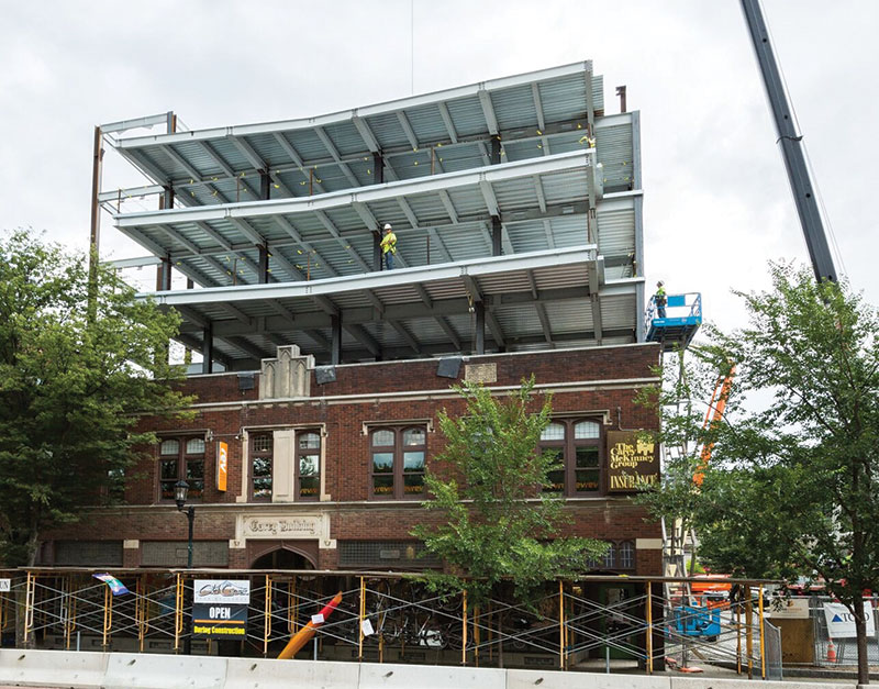
Figure 1a. Carey Building Southeast elevation during steel erection. Courtesy of Gary Hodges Photography.
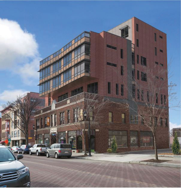
Figure 1b. Carey Building REVIT rendering of Southeast elevation. Rendering courtesy of John Snyder Architects.
The expansion or “overbuild” is composed of a steel superstructure with 5½-inch lightweight concrete floor slabs on 2-inch composite steel deck. The lightweight concrete system was chosen to create a 2-hour barrier between floors without fireproofing the steel floor deck. The structure’s lateral restraint is provided by a hybrid lateral force resisting system. The concrete and masonry elevator shaft located towards the North East corner of the structure provides the primary lateral restraint. Due to the eccentric position of the shaft, which was required to provide the client’s prospective tenants open assembly space at multiple floors, the applied lateral forces do not coincide with the center of rigidity of the shear wall system. The consequence is additional lateral torsional forces, creating excessive building drift. To maintain the total drift level to less than L/500, the design required a series of steel braced frames to pass though the core of the existing and new building (Figure 2). The “overbuild” columns are located directly over the existing reinforced concrete columns. To ensure a successful design, the existing structure required an extensive structural analysis to locate building elements that needed to be bolstered to support the additional gravity and lateral loads.
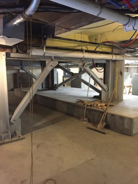
Figure 2. Center core braced frame
at basement level.
The first phase of the project was to analyze and reinforce the existing foundation. Based on initial field investigations, the original foundation was recognized to be composed of shallow caissons, possibly hand dug. Discovered during construction were three existing foundation types: strap footings at the West wall columns, shallow caisson foundations, and typical spread footings. The methodology used for the existing foundation redesign, to ensure sufficient bearing capacity and to mitigate unwanted settlement, was to ensure that the existing foundation did not support any additional load. The foundation loads increased from a typical load of 180 kips to a maximum total new foundation load of 360 kips. The decision was made to support this additional load on the new foundation elements. The new design requires the enlargement of the existing foundations with reinforced concrete “footing extensions” doweled into the existing foundations (Figure 3 and 4).
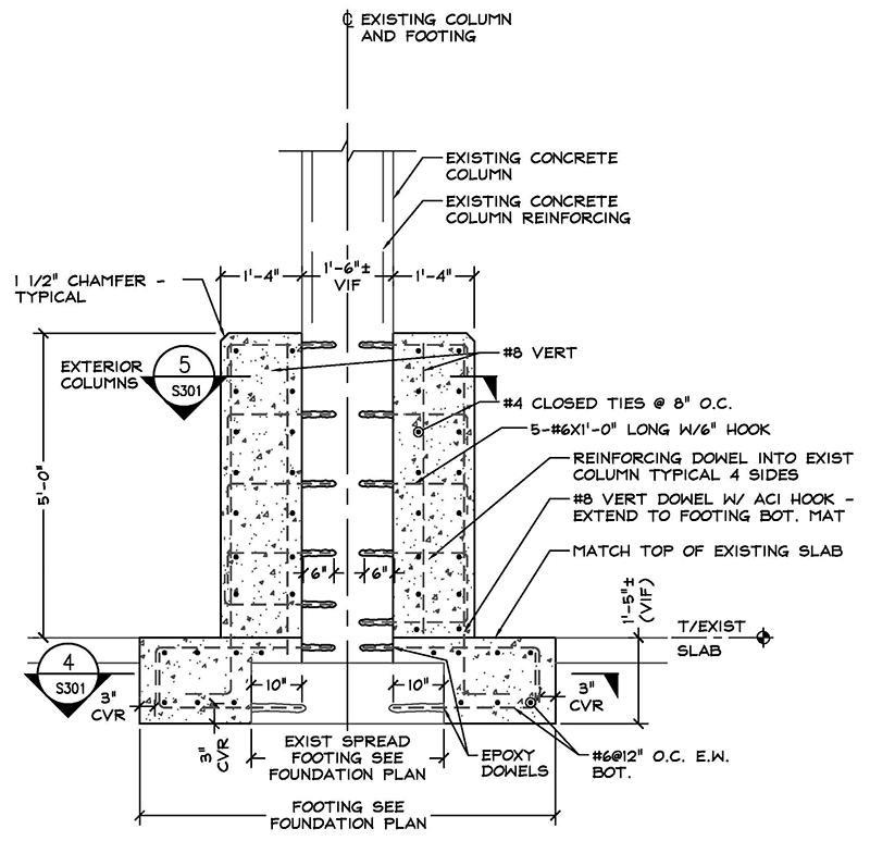
Figure 3. Footing extension reinforcing typical detail.
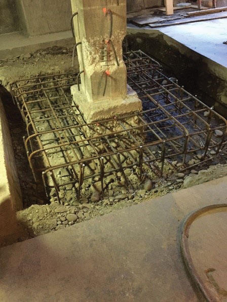
Figure 4. Footing extension reinforcing at existing caisson foundation.
A primary concern was the amount of reinforcing in the existing foundations. The existing footing depths vary from 18 and 26 inches; therefore, the only reliable method of determining the size and location of existing footing reinforcing was by destructive testing. In lieu of extensive destructive field tests, the existing footings were treated as plain concrete when designing the footing extensions. With the assistance of a reinforced concrete collar used to supplement existing column reinforcement at the basement level, most of the footing extensions do not require an additional reinforced concrete “cap” over the existing footings. A concrete cap was required at one braced frame foundation (Figure 5). The additional concrete cap self-weight also serves to completely mitigate foundation uplift at this location.
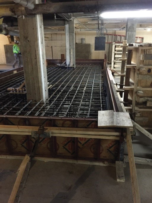
Figure 5. Braced frame uplift resisting mat footing.
The second phase of the project was to reinforce the existing concrete columns. Ground Penetrating Radar (GPR) testing was successfully performed on each existing column, along with selective destructive visual inspections at each level, to evaluate the existing column reinforcing. The tests proved essential, as no reinforcing was detected in the lower portion of the basement level columns. To support an additional five-story steel structure, the columns were strengthened with a reinforced concrete collar. The collar consists of a 1-foot 4-inch reinforced concrete band wrapping the existing column (Figure 6). The original redesign called for a less intrusive stepped collar, but the as-built collar was found to be more constructible and still allowed for acceptable storage space. The reinforcement within the collar provides the much needed confinement of the existing concrete columns. The collar is also helpful to reduce the moment arm between the center of the existing assumed plain concrete footing and the new footing extensions.
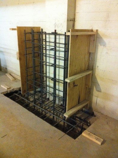
Figure 6. Existing column concrete collar reinforcing.
The third phase of the project was the placement of the elevator shaft foundation. The foundation was designed with the assistance of underground engineering specialist Brierley Associates, headquartered in Syracuse, NY. The elevator shaft is constructed of 12-inch cast-in-place reinforced concrete up to the new third floor level and 12-inch reinforced masonry to the roof level. As a primary component of the lateral force resisting system, not only is the elevator shaft tasked with providing gravity support for the adjacent framing, but also with resisting wind and seismic event forces. With an aspect ratio of nearly 8V:1H, bending controls the shaft design. Also, the slender elevator shaft walls introduce significant uplift forces to the foundation. To resist the uplift, (8) 8-inch diameter micro-piles were uniformly spaced around the elevator shaft foundation and socketed 25 feet into bedrock located 30 feet below grade. Problematic to the design was how to transfer the uplift forces between the elevator shaft shear walls and the micro piles. The solution was to weld a series of ½-inch shear studs to the micro piles and extend the pile shaft directly into the elevator foundation walls, thereby lapping the pile casing with the foundation wall vertical reinforcing. The micro-piles also served a critical function during excavation for the elevator pit and pile cap. The elevator shaft is located within 2 feet of an existing column and in close proximity to the earth retaining exterior basement wall. The 8-foot deep excavation necessary for the elevator foundation would undermine both soil bearing elements. A plan was devised to create a support of excavation (SOE) system using the micro pile casings that would extend up to the basement floor elevation and become cast into the foundation wall (Figure 7). The SOE utilizes a typical soldier pile and lagging scheme, with the micro piles serving as the soldier piles. Six-inch WT standoffs were welded to the outside of the soldier piles to create a void space between the lagging and the micro pile casing. The void space permitted concrete to flow between the lagging and the casing, completely casting the micro pile into the elevator shaft foundation wall.
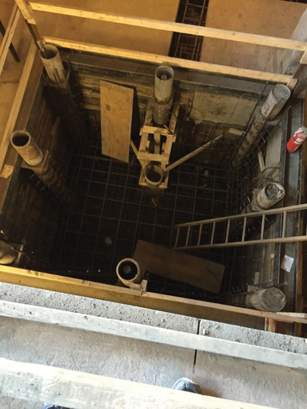
Figure 7. Aerial view of micro pile support of excavation at new elevator shaft.
For the Structural Engineer, the design and development of a vertical expansion over an existing structure is a unique opportunity to preserve and reuse the original building’s form and function, while creating new space for a more comprehensive use of the building site.▪
Project Team
Structural Engineer: Elwyn & Palmer Consulting Engineers, PLLC
Owner: Travis/Hyde Properties, Ithaca, NY
Geotechnical Engineer: Elwyn & Palmer Consulting Engineers, PLLC
Foundation Design: Elwyn & Palmer Consulting Engineers, PLLC with Brierley Associates
Architect: John Snyder Architects, Ithaca, NY
General Contractor: Lechase Construction, Rochester, NY